Introduction
Check underneath the Introduction for any potential Important notes! Do not skip these before starting the guide, please.
Valve Inspection and Adjustments can be a daunting task if it is your first time, even with the manual with you. My attempt at it initially took me months of waiting for parts, not knowing what to do exactly, and not doing it properly. After having to do this process a few times it will probably take me two to three hours if I work on this in one go. Don't worry though, in this guide I will take you through this process step-by-step.
Your first time will not necessarily have to take 8 hours but do expect to work on it the whole day assuming you have all the tools ready. If you are lucky you will only need to do the inspection which will only take about half an hour to an hour max. You will unfortunately have to do a bit more if you need to do some adjustments as well.
I would recommend doing this inside, When I initially did this I did not have a garage and had to work outside in the sun. If this is you buy something to put over your motorcycle if you are not done within that same day. This is to avoid any debris getting into your valve intakes.
To justify the cost to the wife, explain that pretty much all the tools you are going to need can be used for any purpose besides the bike, it's not an exclusive one-time tool. So don't feel bad for spending the money to buy the tools.
I've listed out the individual tools you will need but you can probably get a better deal buying the tools in a "package" instead of buying an individual socket. The choice is yours in that department. Walmart sells tool kits for thirty bucks which will have a good amount of sockets, wrenches, drive ratches, and probably some Allen keys.
Now why do you need to do adjustments in the first place?
After some time the shims can expand which will close the amount of tolerated distance for the valves. This can lead to overheating, power loss, pre-ignition, or burnt valves.
As I said before this can be a daunting task to start, but in all honesty, there isn't much to it. It just takes a lot of time and patience. Hopefully, with this guide, this will be all you need instead of having to scour through forum posts, youtube videos and having to read the manual a few times. (You will definitely still need the manual though, lucky for you I will include the pages needed.)
If you have any questions feel free to ask them. I won't be able to answer every single one but I will certainly try my best!
Note: First few steps will be from other guides from my fellow editors. I will add their names to this Guide later: Work in progress.
Note 2: You can skip parts 10-17 if you won't need to adjust your front valves as the tensioner will be almost impossible to access without doing so.
-
-
If you have frame covers below your seat, remove them by removing the 4 mm allen bolts holding them on. Use a 4 mm allen wrench to turn the screws counter-clockwise until they come off.
-
Once the frame covers are off, remove the 4 mm allen seat bolts on both sides of the seat. Use the 4 mm allen wrench to turn the screws counter-clockwise until they come off.
-
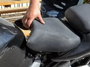
Lift the front of the seat, then pull it off the frame.
-
-
-
Remove the radiator cap security screw with a Phillips #1 screw driver by turning it counter-clockwise.
-
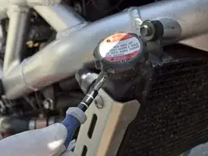
Remove the radiator cap by pressing down on it and turning it counter-clockwise until it can be lifted off the radiator.
-
-
-
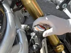
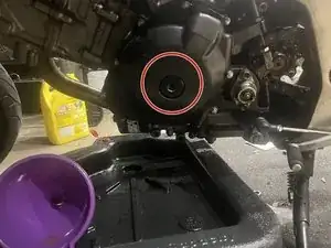
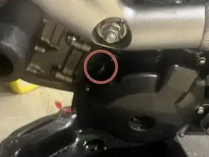
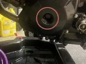
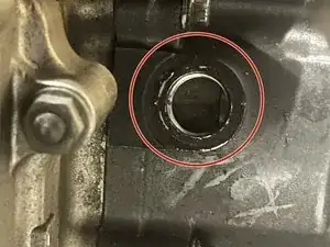
Locate the 10 mm hex coolant drain plug. It is on the right engine cover, just below the coolant outlet.
-
Turn the coolant drain plug counter-clockwise with a 10 mm socket wrench or box end wrench until it can be turned freely by hand.
-
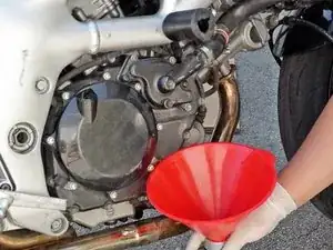
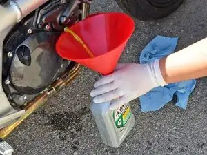
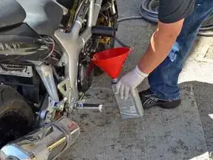
Place a container under the drain plug to catch the coolant when it streams out of the coolant drain hole.
-
-
-
Finish removing the drain plug by hand and allow the coolant to drain into the container.
-
Once the draining coolant has slowed to a drip, stand the bike up vertically to allow the last of it to drain.
-
-
-
Put the coolant drain plug back in its hole and turn it clockwise with a socket wrench or box end wrench until it is snug.
-
Place the radiator cap back over the filler hole and turn it clockwise until is snug.
-
-
-
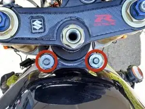
Turn the two 4mm allen bolts in the front tank mounts counter-clockwise with an allen wrench until they come out.
-
Turn the two 12mm hex bolts in the tank's hinge base counter-clockwise with a socket wrench or box end wrench until they come out.
-
-
-
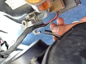
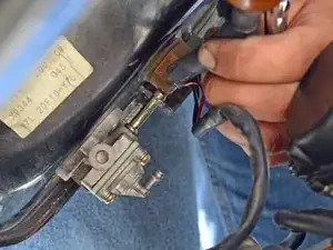
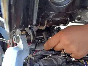
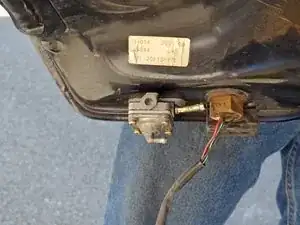
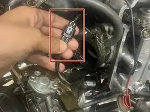
Disconnect the fuel level sensor connector, located near the tank hinge base. It will be a three wire connector and one side of the wire will be traceable to the underside of the tank.
-
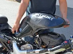
Carefully lift the front of the tank to gain access to the hoses attached to the tank.
-
-
-
Locate the petcock on the left underside of the tank. It hill have 2 hoses attached to it and will be next to the fuel level sensor.
-
Disconnect the vacuum hose from the petcock.
-
Disconnect the fuel hose from the petcock
-
Disconnect the tank breather hose from the base of the tank.
-
-
-
Carefully lift the tank up and off the frame of the bike, being sure that the fuel level sensor wire does not get caught in the frame.
-
-
-
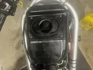
There will be two hoses connected on the rear left side of the air box. There will be two clips that will hold these hoses to the air box. These will allow all the excess oil to collect in a small spong-like section. After this is disconnected slowly pull the air box from the carburator
-
-
-
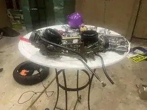
Slowly pull this out, this allows the vacuum to pull the necessary amount of gas from the tank into the carbs. As we will completely remove the carburetor from the motorcycle.
-
-
-
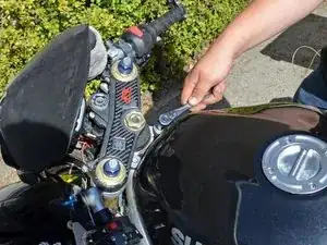
Before pulling the carbs off loosen the clamps on both the front and rear. Use your JIP-4 Screwdriver
-
-
-
Slowly pull from the top "gold" handle towards you. Do this from the opposite side of where you are pulling. You will need to use some strength but not a lot. This should easily disconnect the carb from the head
-
-
-
Start by grabbing your JIP-4 screwdriver and slowly removing the screws. If they have never been touched before they can be hard to remove. Try your best not to strip these. After you are done with the first slowly pull the cable out of the carburator "body". Repeat the same caution for the second choke cable
-
-
-
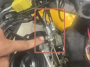
Loosen the throttle cable nuts until they can be removed completely
-
Afterwards pull the cables out, you may need to use the screwdriver to push them out completely
-
-
-
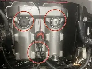
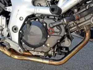
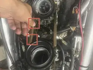
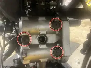
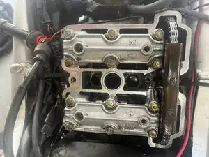
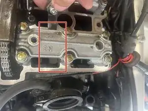
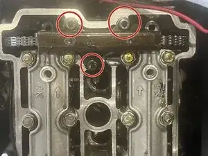
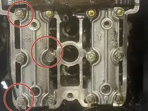
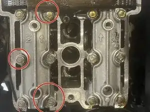
Use a 6 mm Allen Socket to remove all three of these. They hold the cover down on the front and rear heads.
-
-
-
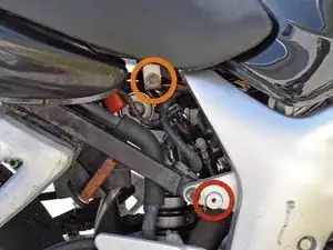
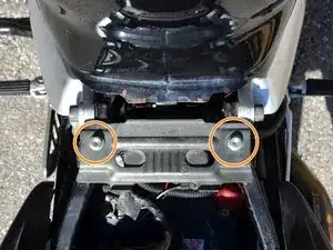
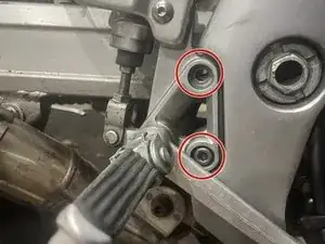
Unscrew these two bolts with your 6mm Allen Socket.
-
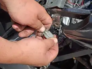
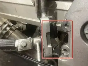
Unhook this from the break and foot rest. This is your rear light. Very important that you do not break or forget to reinstall later!
-
Tuck the rear brake/footrest onto the tire, easiest and most time efficient thing to do an won't damage anything if you push the foot rest in
-
-
-
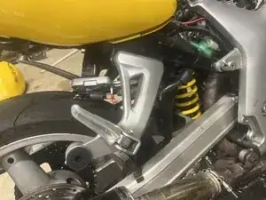
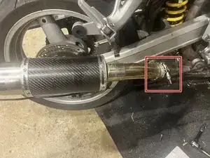
Loosen the clamps on your exhaust and remove this. It is not 100% necessary to do this step but will make working with the tensioner a little easier. It only takes a few minutes anyways
-
-
-
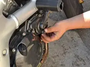
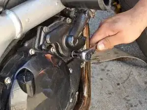
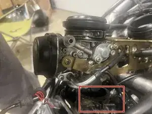
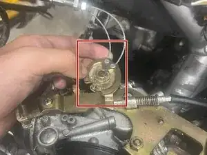
Unscrew this with a 10mm Allen Socket.
-
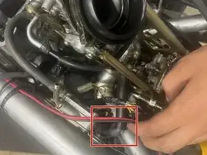
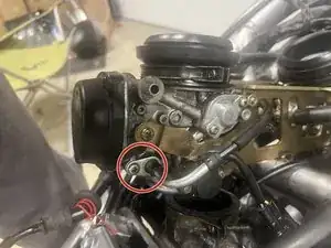
Unscrew the second screw with a 8 MM Allen Socket. We will be able to see if the bike is at TDC and put it on F or R depending on which one we are checking
-
-
-
Turn over the engine with a 18MM Socket ( I would recommend using a small extention) and turn counter clock wise until you can see the R
-
-
-
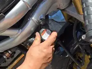
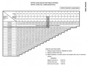
Stick the feeler gauge from the inside out underneath the valve. Try the biggest allowed tolerance and work yourself down or up to see when it finally tightens.
-
-
-
If you are within the tolerated clearance then congratulations, you have reached the end of this guide, lucky guy.
-
If not it really depends on if you need to do only the rear or also the front (or vice versa).. In that case, you're in for a long ride
-
-
-
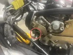
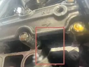
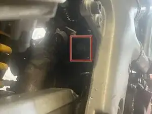
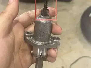
We will now bring our attention to the rear cam chain tensioner. Use a 10mm Socket and remove the middle screw. Grab your expensinve little 80 dollar tool and insert it in the middle and rewind the tension.
-
-
-
use a 10mm socket and remove the screws asshown on the pictures. This is to avoid too much tension on the cover. I have broken them before by not doing this (with installation, but its good practise to do it with removal as well) Do this for both covers
-


To reassemble your device, follow these instructions in reverse order.
