Introduction
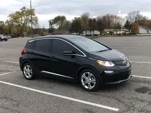
This guide will help with the installation of a powered trailer light wiring harness converter. Wire color identification and component locations should be the same on any 2017-2021 (Pre-Facelift) Chevrolet Bolt EV.
Watch this Crutchfield guide on how to tap into a wire with solder and tape. This is basis of how the vehicle's wire harness is manufactured (wrap wires together, sonic weld, tape) so nothing unusual there.
As tempting as it may be, please DO NOT use the wire tap connectors included in some kits. There are many problems with their use - read more here.
Lets review the trailer light converter chosen for this installation. You may have researched this topic and found others installing a 4-pin trailer lighting kit that relies on inductive clamp pickups. This is nice because it protects the integrity of the vehicle wiring (no cutting), but it is also expensive at almost $200 and easy to install incorrectly. The inductive clamps sense current traveling through the wires to each function, but if installed backwards the trailer lights either operate out of sync with the vehicle lights or not at all. There's also a calibration sequence that can be lost if the vehicle's 12 volt battery is removed.
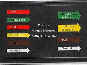
For simplicity and cost, I've chosen to install a powered trailer light converter module protected by a fuse. Links available in the parts list above. Opt.1) is meant to be plugged into a different vehicle's existing wire harness as an optional add-on and includes an inline fuse holder. The same basic converter unit is included as the Opt.2) Universal Kit, but that one does not have an inline fuse holder. If you should choose the universal or another kit, be sure to include a fuse especially if you will be tapping into the Bolt EV's same harness connection for +12V. The fuse is important to protect the vehicle's onboard lighting functions.
Opt.1) requires cutting off the input connector and tying each wire into the Bolt EV's wire harness. The guide will help identify each wire color and function to connect. There are only six connections including +12V Power, Ground, Stop, Tail, LH Turn, and RH Turn. Lets get to work!
-
-
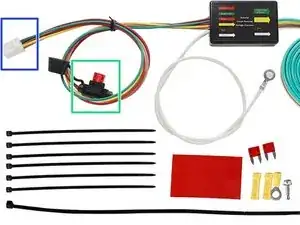
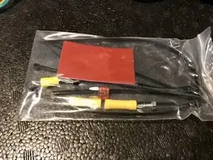
This kit is made for a '17-'22 Honda CR-X, but that's not what we care about
-
The +12V input wire has an inline fuse holder! Universal kit does not
-
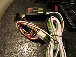
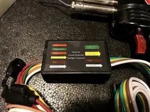
If the input plug is chopped off, we've got the same module and wire colors as the universal trailer light converter kit
-
Links available in the Parts List at the top of this guide, or search Amazon
-
B08N6F5X7Z (Opt.1: CR-V)
-
B08N68MNSL (Opt.2: Universal)
-
The best part is, at the time of writing, the CR-V kit is $6 cheaper than the universal kit
-
-
-
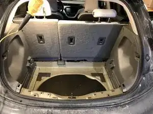
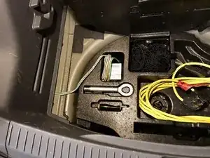
Remove everything from the cargo area beginning with your stuff. Also including the fabric shade, false floor (if installed) and carpet
-
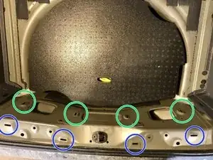
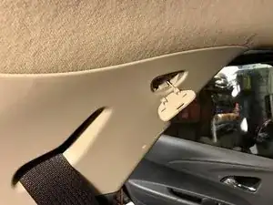
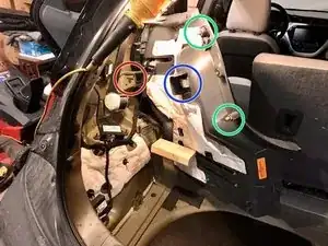
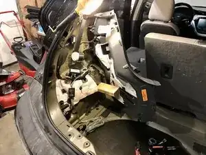
Using the pictures to the left, identify where the panel clips are located and begin to pull towards the front of the car from the bottom of the panel focusing effort where the clips are
-
With the vertical portion of the panel un-clipped, pull up to remove the rest of the clips from the horizontal surface. The panel will come out from under the hatch gasket
-
-
-
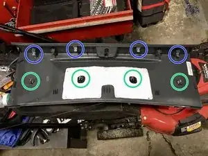
Check to see if any of the clips came off the panel and stayed in the sheet metal
-
Carefully bend them back into shape and reinstall onto the panel as required
-
-
-
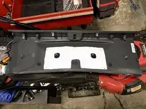
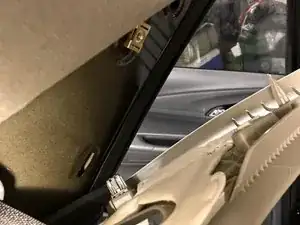
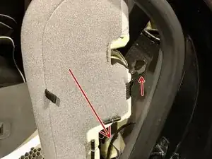
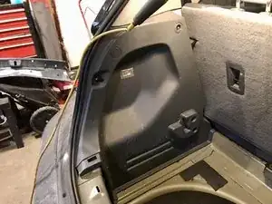
Note location of clips from pictures at left and carefully pull the panel off
-
Slide the trim piece down the seat belt where it will stay for a little while
-
-
-
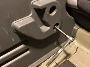
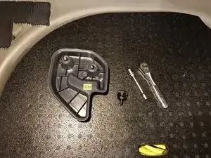
Using a 10mm deep socket, or 10mm socket and extension, remove the cargo shelf support
-
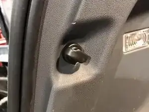
Unscrew the cargo net hook by hand
-
-
-
Carefully pull the side panel beginning at the hatch opening noting the location of each clip on the left
-
Disconnect the cargo light wire
-
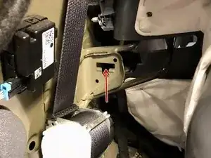
Release the tab for the rear seat side bolster
-
-
-
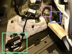
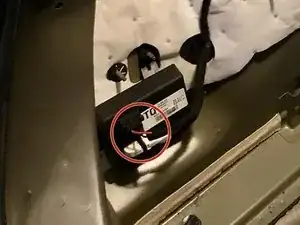
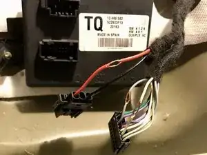
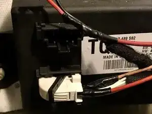
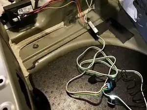
The top two pin connector will provide power RED WIRE = +12V
-
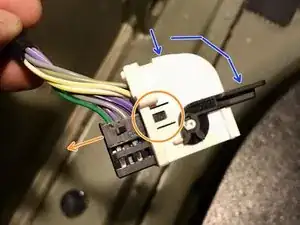
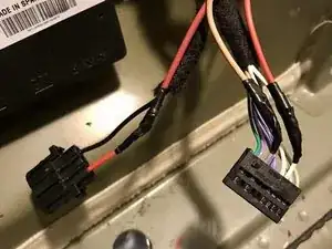
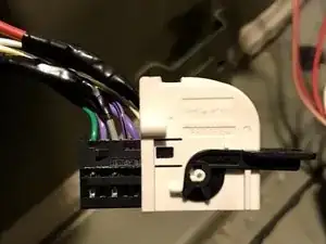
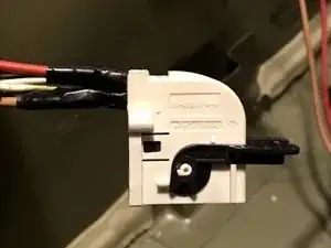
Push the ribbed tab to release the locking lever on the white connector and pull it out of the module
-
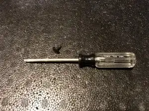
Remove the white lever lock cover from the 18 pin connector to help identify the wires. Lift the clip with a small flat head screwdriver to slide the connector out
-
-
-
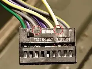
The 18-pin connector has tiny numbers 1 on the left and 9 on the right, indicating the pin numbers
-
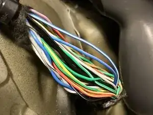
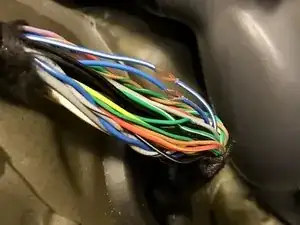
PIN 3: GREY/BROWN = TAIL
-
PIN 7: WHITE/YELLOW = STOP
-
-
-
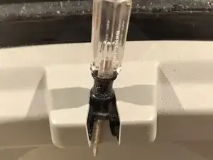
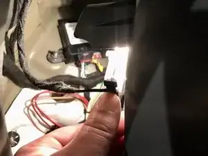
Use a utility knife to carefully shave the insulation off of each signal wire
-
Gently open the strands of copper wire with the tip of the utility knife
-
Strip the end of each trailer light module wire, insert through the vehicle signal wire, twist, solder and tape
-
-
-
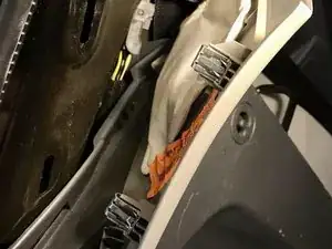
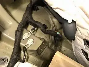
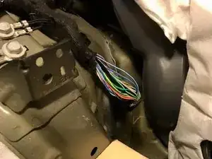
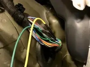
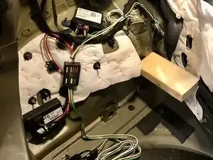
Carefully cut into the fuzzy tape covering the wires that make up the bumper harness
-
Expose enough of the wires to be able to look through them, about 4-6 inches will need to open up
-
-
-
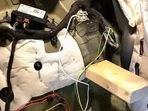
Remove one of the ground bolts and install the ground wire from the trailer light converter under it
-
-
-
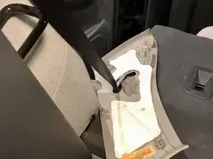
"Close" the liftgate latch - push a screwdriver into the latch to simulate the hatch being closed
-
Listen for two solid clicks
-
A switch in the latch will tell the car to use the brake lights on the liftgate
-
-
-
Using a multimeter, test light, or 4-pin trailer light tester, check the function of the light converter
-
A snow brush from the drivers seat to the brake pedal can help test the Stop function
-
Hazard lights check the LH and RH Turn functions
-
Headlight control switch, or the key fob Unlock or Lock buttons activate the Tail function
-
-
-
Tidy the wires with included zip ties mindful of the space available when the panel is reassembled
-
Trailer wiring will pass under the bottom of the trim panel
-
-
-
Reinstall the Rear Seat Bolster, Left Panel, C-Panel Trim, and Bottom Trim Panel
-
Reinstall the Cargo Net Hook, Carpet, Cargo Shelf Support, and Cargo Shelf
-
-
-
If you have any trouble, or would like to suggest an update to the guide, I'm on Reddit u/intrepidzephyr
-


To reassemble your Bolt EV, follow these instructions in reverse order.
