Introduction

The motherboard directly connects almost all of a device’s parts. If your motherboard is having problems or has failed, you may decide to replace it. This guide will demonstrate replacing a motherboard for the Acer Iconia Tab A501.

  1. 4eXEkKNX1ZDBtK1y
    4eXEkKNX1ZDBtK1y
    T4B1xjJCCHvnyAWn
    mECZH6AlgV13y1YQ
    • Turn off your device before opening it.

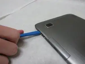
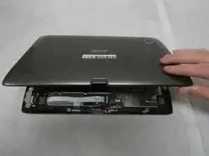
    • Use a plastic opening tool to carefully separate the back cover, starting at the volume buttons.

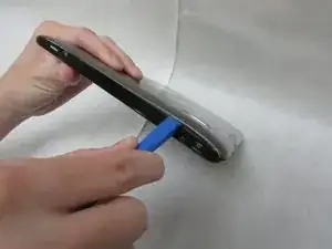
    • Continue separating the back cover along the short side closest to the camera and around the device.

  2. TJWQQdBWE5YOZHgi
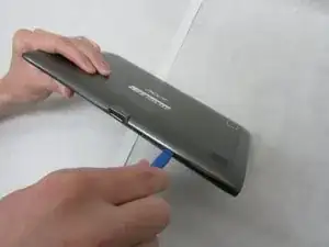
    • When separated enough, a little more than halfway around the device, the back cover will be easy to take off.

    Can this be combined with the previous step? I think you could lose one of the images before to condense.

    Alex Watkins -

  3. rUVS6LEpXgWyNnSy
    • Remove all tape from the device.

  4. MqADFcvBVFTDojqR
    MqADFcvBVFTDojqR
    avIxSVcALIMLqn3O
    oxjcI6SiaZUUR2MD
    • In the next step, be careful not to squeeze too hard or scratch the motherboard.

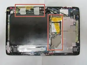
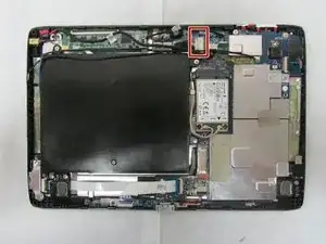
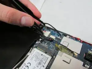
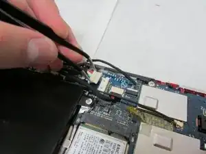
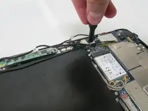
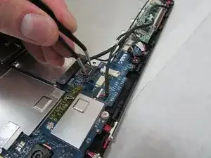
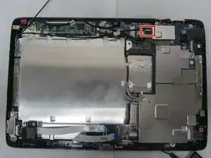
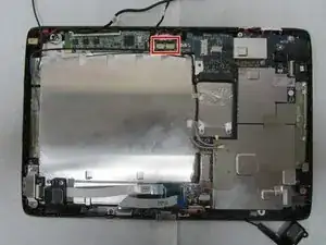
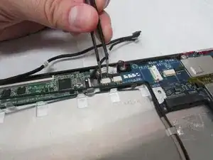
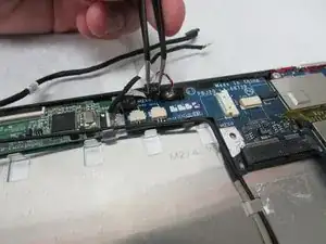
    • Use the angled tweezers to disconnect the motherboard-battery cable from the white connector in the middle of the side opposite the docking port.

  5. 6UMNUVUBMi1bq5G5
    6UMNUVUBMi1bq5G5
    En24YcMYOwZUx3Ib
    Zjd4K6wlBEk1h2Sw
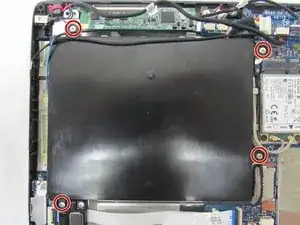
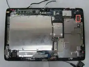
    • Use a Phillips #1 screwdriver to remove the four 4.0 mm Philips head screws connecting the battery to the motherboard.

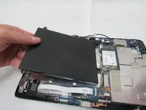
    • Take out the battery.

  6. afon4jCXtCc2We1T
    afon4jCXtCc2We1T
    OFPnnU6CMFDqa5VE
    6Uv6IDORCjglQRXO
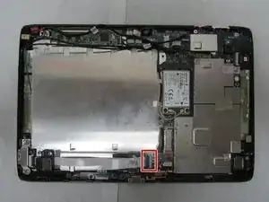
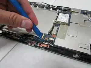
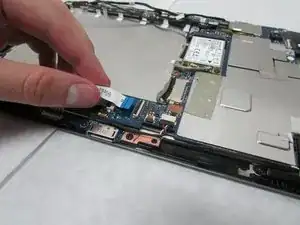
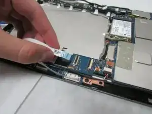
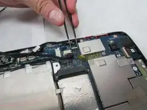
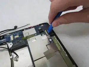
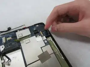
    • Use the plastic opening tool to flip up the locking mechanism on the motherboard connected to the folded, white ribbon cable.

    • Remove the folded, white cable.

    Where is this in relation to the adapter? Consider adding the full device markup image to this step.

    Alex Watkins -

  7. lClTroKjLhMHdAO1
    lClTroKjLhMHdAO1
    WaaB1ToiOghUSQ62
    t6pCLy4rW2CND2V3
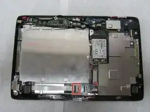
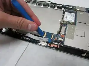
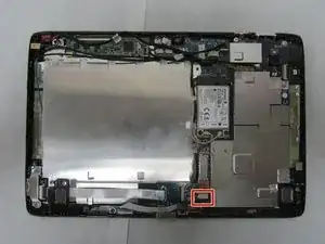
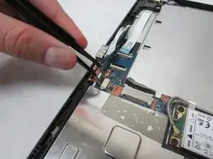
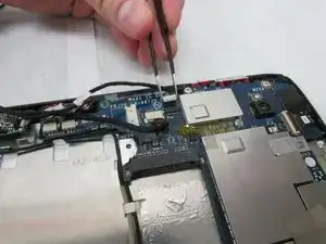
    • Use the plastic opening tool to flip up the locking mechanism on the motherboard connected to the straight, white ribbon cable.

    • Remove the straight, white ribbon cable.

  8. L4HG4B3fuAmxKPid
    L4HG4B3fuAmxKPid
    CTDGC6ieAdfMBghF
    4DYHJeHAnHgwLikJ
    • In this step, be careful not to squeeze too hard or scratch the motherboard.

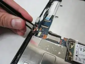
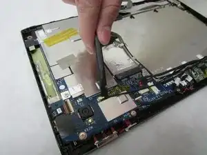
    • Use the angled tweezers to disconnect the cable with red, white and green wires from the beige connector slightly in from the docking port.

  9. LjBp1AUohc6cvjB3
    LjBp1AUohc6cvjB3
    HqtZsM3kH4ZhO4nT
    MbPxypqtBpFUWhTI
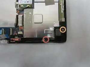
    • Unscrew the 3.0 mm Phillips head screw on the speaker near the Micro-HDMI port using a Phillips #1 screwdriver.

    • Unscrew the 4.0 mm Phillips head screw on the speaker near the Micro-HDMI port using a Phillips #1 screwdriver.
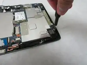
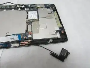
    • Remove the speaker.

  10. 24WWbZB4wPtXxY5o
    24WWbZB4wPtXxY5o
    flthimDaZCTySJxB
    l4HlaDjFGJMVxVaF
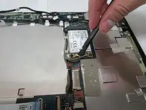
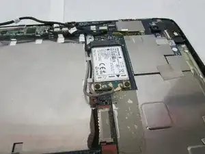
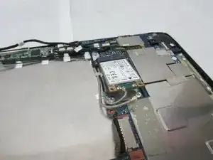
    • Use the flat end of the standard Spudger to disconnect the two small, rotatable connectors attached to the wireless adapter.

  11. E2GXsX1ZMlGl2sGW
    E2GXsX1ZMlGl2sGW
    AtyxcrMoDOOJLHDX
    PkTGBP3BresmLrOE
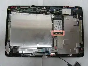
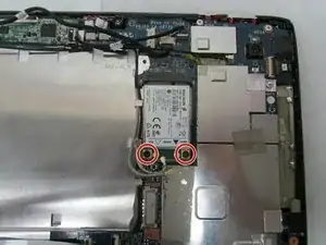
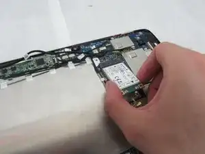
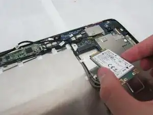
    • Use a Phillips #1 screwdriver to remove the two 3.0 mm Philips head screws holding the adapter down.

  12. fH2CrrjQAnw4sRRQ
    fH2CrrjQAnw4sRRQ
    4TajBoGlnHksiVsa
    • Carefully slide the adapter out to remove it.

  13. bBkhLmaeSoFMAC3g
    bBkhLmaeSoFMAC3g
    qvFN6u31q62pt5Oq
    3NvXHvGuRWEAqTpV
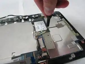
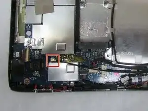
    • Use the wide end of the standard Spudger to take off the rotatable connector to the 3g antenna below the rear-facing camera.

  14. IFjEgFqhbCLjKUlE
    IFjEgFqhbCLjKUlE
    GlE6ZCr1j6Ew6xeG
    kd2ph6M44mwJODWp
    • In the next step, be careful not to squeeze too hard or scratch the motherboard.

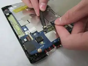
    • Use the angled tweezers to disconnect the cable with red wires from the beige connector opposite the docking port.

  15. CdZiaieNZDfNfF4F
    CdZiaieNZDfNfF4F
    wFhPD4WLGMNbrBXK
    bAkXFWSaFvBgXapb
    • In this step, be careful not to squeeze too hard or scratch the motherboard.

    • Use the tweezers to remove touchscreen connector from the motherboard.

  16. sMWPNyydQ3YnXXx4
    sMWPNyydQ3YnXXx4
    UiQQqrdB3kkUnAKM
    TNrMER3sGL1XKOcR
    • In this step, be careful not to squeeze too hard or scratch the motherboard.

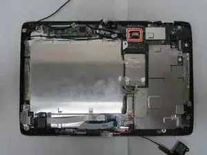
    • Use the angled tweezers to disconnect two microphone connectors, which are above the orange-brown touchscreen connector and next to the battery space.

  17. JLtLEX4HZrKV1SCS
    JLtLEX4HZrKV1SCS
    wIvG4UH33uc6PIDa
    JhjMpKYcGgwdYT3V
    • Use the plastic opening tool to flip up the locking mechanism to the white front camera port just above the rear-facing camera.

    • Disconnect the camera cable from the motherboard.

    What is the tab in the last picture? Does something need to be done with it? It looks like you’re removing it with your fingers, not the plastic opening tool.

    Alex Watkins -

  18. KCgxNXdaxtI6eeXJ
    KCgxNXdaxtI6eeXJ
    AVpEPMYRGVXEsAR3
    WMdbqlNaueniQQeY
    • Use care in the next step.

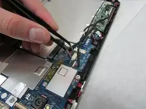
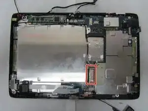
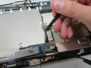
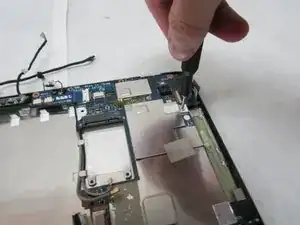
    • Use the wide, flat end of the standard Spudger to disconnect the display connector from the large, metal port next to the battery space.

    What kind of care? Can you be clearer here? Also, at the end, you lift out the connector, right?

    Alex Watkins -

  19. 5ynXGd4H41qq33fK
    5ynXGd4H41qq33fK
    CY5WRgJN3EO2m15q
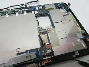
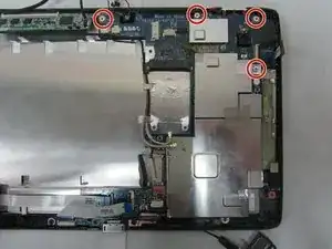
    • Use a Phillips #1 screwdriver to unscrew the four 4.0 mm Phillips head screws holding the motherboard in place.

  20. DmmDbDAESJWlVSUH
    DmmDbDAESJWlVSUH
    ZHijgpSmZJ5XZJGX
    k5beFmFXa2m3KcBa
    • Remove the motherboard.

Conclusion

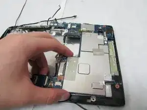
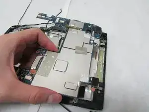
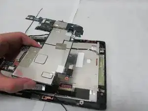
To reassemble your device, follow these instructions in reverse order.

Daksh Malhotra

Member since: 08/07/19

1383 Reputation

0 comments