Introduction

This guide will teach you how to remove and replace the ports (USB/Audio Jack/Microphone Jack/E-SATA) of your Asus U50 Series laptop. You may want to replace these ports if any of them are unresponsive or not working. For example, if you were to insert multiple USBs in the same port and the computer was not recognizing any of them, this is a sign that a replacement is needed. Please note that all ports are on the same panel and must all be removed as one. After that, you may individually work on whichever one needs replacement.

BE CAREFUL when conducting this repair, as there are many loose screws that can easily be lost. Also, there are many bundles of wires which can easily be damaged if they are forcefully and carelessly removed. Lastly, make sure all your components are safely set down and not dropped, as this can cause long term damage.

  1. GD6s6ByGPIM1gMTV
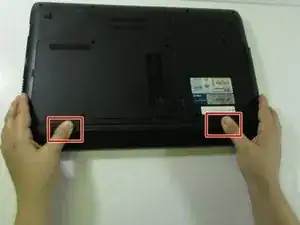
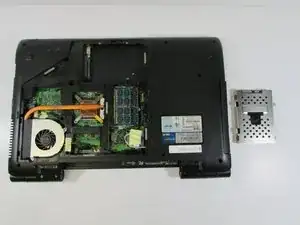
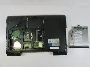
    • Turn the laptop over so the bottom is facing up.

    • Slide the two tabs on the bottom of the laptop toward the edges of laptop.

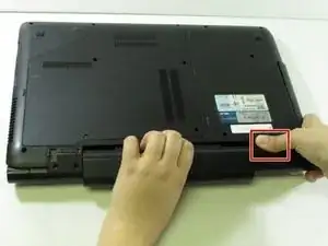
    • Slide the left tab to the left to lock it into the unlocked position. The red showing next to the tab signifies that it's unlocked.

    • You will have to hold the right tab to the right to keep the slot unlocked while removing the battery.

  2. AO2jokPXxAHMBbRi
    AO2jokPXxAHMBbRi
    NNqbDIwFLPwGwWs2
    • Hold down the tab on the right side, then begin sliding the battery out.

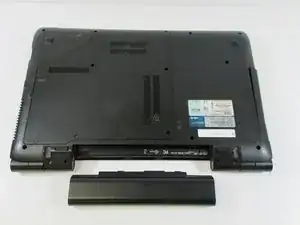
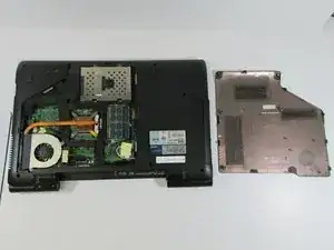
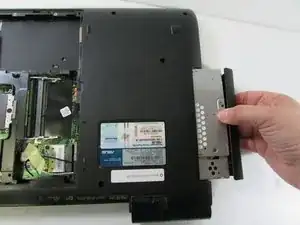
    • Remove the old battery.

    • Next, insert the new battery into the empty slot. Release the right tab to begin locking the new battery into place. Slide the left tab to the right to completely lock the battery into the slot. The red that was showing near the left tab should be gone. This signifies that the battery is locked into place.

  3. FdM3ilPRfRIGlV5u
    • Remove the six screws using a Phillips #1 screwdriver.

  4. 6AKOTbMRGsRZUiy3
    • Pry the lower panel up with your fingernail or a spudger.

  5. DDExULsSWhFFhvVn
    DDExULsSWhFFhvVn
    BUDURMHcyBTH1ajB
    • Lift up on the panel and remove it.

  6. lIqYTMCTTWBgPvDF
    • Remove the two screws using a Phillips #1 screwdriver.

  7. TO5ggdkgIIATMfZR
    TO5ggdkgIIATMfZR
    XPKKVCFmWZaZlLqp
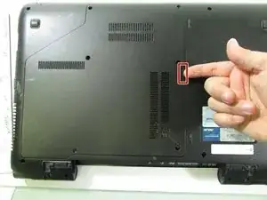
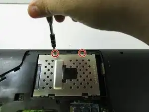
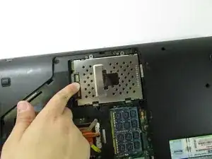
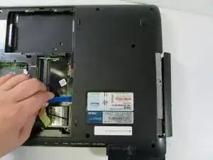
    • Using your finger, push the hard drive back.

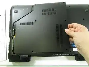
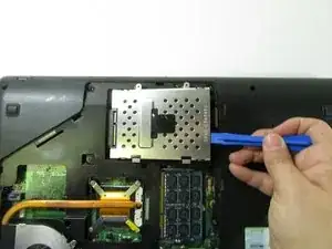
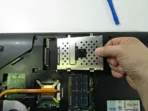
    • Pry up the drive with an opening tool (or your fingernail).

  8. 4coiRRXNLVYOU3Ws
    4coiRRXNLVYOU3Ws
    CkNoS4qFKsuJaoth
    • Pull back on the hard drive and lift upwards.

    • Remove the component completely.

  9. ApMPBHyd3TRgZeU2
    • Remove the single screw.

  10. g2ci2tomHPWBm3Q2
    • Use the plastic opening tool to push the drive out from the back.

  11. XL4RhWI3IYFiLgKK
    XL4RhWI3IYFiLgKK
    XN55jawjWHwRCnuw
    • Pull the drive out and remove completely.

    • When reassembling the drive, lay the laptop with the base towards the floor. Then, push the drive all the way in. Otherwise, the drive will become stuck and be difficult to reassemble.

  12. 5qLKYqMWNPiFgFYB
    5qLKYqMWNPiFgFYB
    WX1fyXYsNijPBrvt
    5jKSvNZRNTLlXbgv
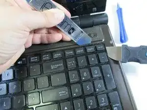
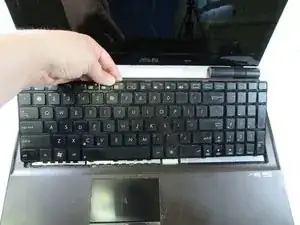
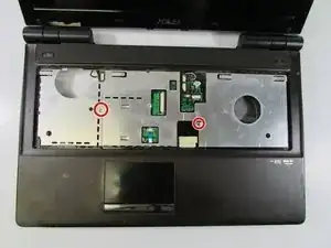
    • Insert one of the pry tools under a top corner and the other tool under the side of the same corner. Make sure to get under the metal of the keyboard, not just the first layer of plastic. Then pry the corner down and out from under the little overhang its sitting under.

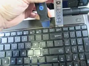
    • Next, slide the pry tool on the top over to the next overhang and insert the second tool on the other side. Push down and pry out the keyboard.

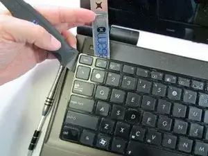
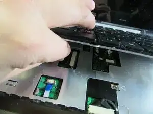
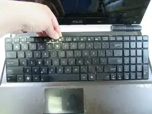
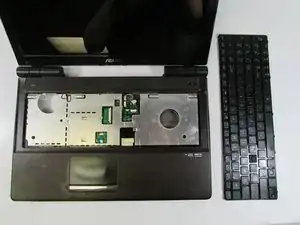
    • Repeat the same process all the way down to the opposite corner.

  13. sMhDGPxkR5ASBPw1
    sMhDGPxkR5ASBPw1
    N5Xqc5FJglQfOfkd
    • Once the keyboard is free, lift it up slightly and release the cable connection underneath.

  14. OoA1whuva5CMC6fJ
    OoA1whuva5CMC6fJ
    seUACtB4xssekd6F
    • Last, remove the keyboard completely from the computer.

  15. CMEa1bMiW5JrAO1e
    CMEa1bMiW5JrAO1e
    JXLkr1WFbW2mLKJk
    • Push back on the silver clips shown in the picture until you hear/feel a pop.

  16. 1PtE1XoZHyL4BaXx
    1PtE1XoZHyL4BaXx
    AtnQIPeUqigHIlWD
    • Pull back on the RAM card and remove it.

    • Repeat for the lower RAM card.

  17. FKTvBtrQBMKuwt3W
    FKTvBtrQBMKuwt3W
    vIW4jcsya6CFAFHM
    qTRLiuAKCsUUusOG
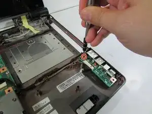
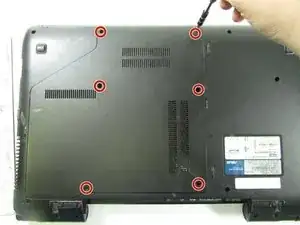
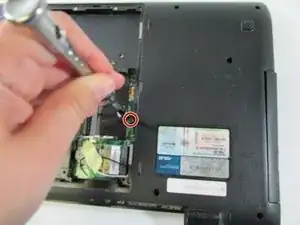
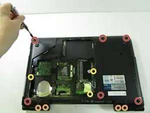
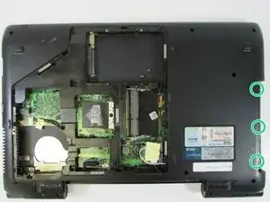
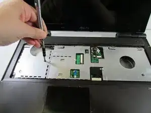
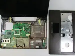
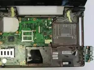
    • Remove the six screws from the outer lower case.

    • Remove the four screws from the hinges.

    • Remove the three screws on the inner lower case.

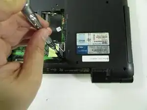
    • Remove the three screws from the optical drive area.

  18. 2iZtOARBK6cfwiRA
    2iZtOARBK6cfwiRA
    oTSEHVdtHiagsqkF
    • Remove the two screws from the metal frame.

  19. xPwrENSeuWetAPqw
    xPwrENSeuWetAPqw
    OwVUOQeJAZCoVJqF
    gUnhUsKwNYNvcnXi
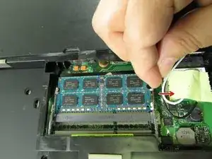
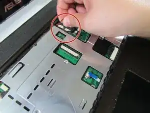
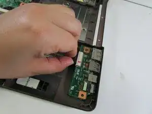
    • Pull the two bundled cables away from the connector in the same direction as the individual wires are running.

    • Potential for device damage: Pull evenly on the full width of the cable so that no individual wires are overly strained.

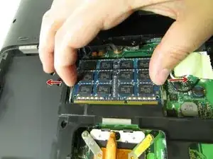
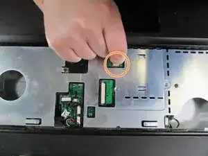
    • Pull the no-fuss ribbon cable straight out of the connector.

    • Potential for device damage: These kinds of connectors are fairly rare, so check carefully for a way to release the connector before you resort to pulling on the ribbon cable.

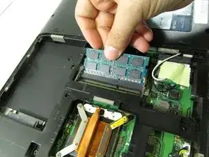
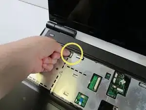
    • Pull the single bundled cable away from the connector in the same direction as the individual wires are running.

    • Potential for device damage: Pull evenly on the full width of the cable so that no individual wires are overly strained.

  20. JIylv61dHBNJveQw
    • Lift up and remove the upper case.

  21. ZMmRiDttsQ3Hg3eR
    • Remove the single screw.

  22. PlRNGaLfvgP2FGBD
    • Pull the cable away from the connector in the same direction as the individual wires.

    • Pull evenly on the full width of the cable so that no individual wires are overly strained.

  23. 62LclIuMXn5qbp1T
    • Lift up and remove the port panel.

Conclusion

To reassemble your device, follow these instructions in reverse order.

Kelly Greeling

Member since: 07/02/17

1032 Reputation

0 comments