Introduction
If none of the functions of the Brother MFC-490CW are working, the motherboard may need to be replaced. This can occur if the device has experienced an electrical surge that overloaded the motherboard.
-
-
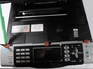
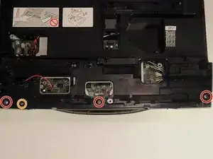
Use a Phillips #2 screwdriver to remove the three 12.1 mm screws holding the control panel in place.
-
-
-
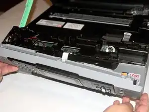
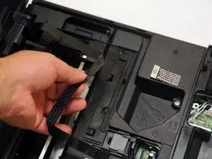
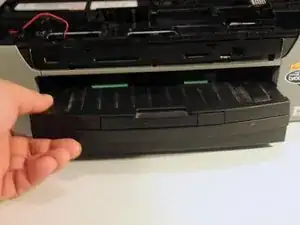
Lift up the front panel from the device.
-
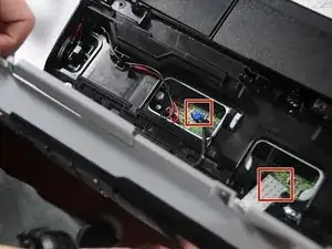
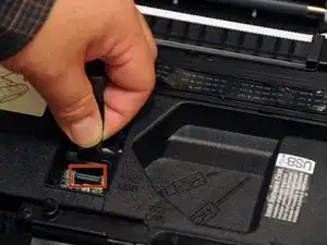
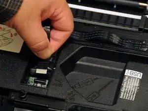
Gently lift up and disconnect the data cables that attach the panel to the printer.
-
-
-
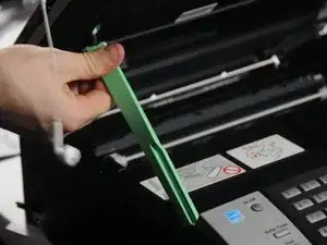
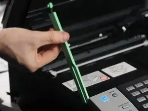
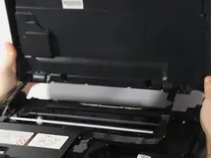
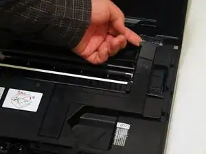
Lift the scanner unit lid.
-
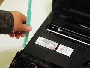
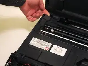
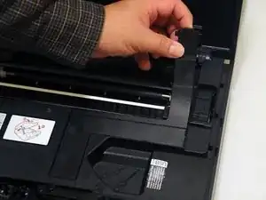
Gently twist the top portion of the arm. The top portion should release from the scanner unit.
-
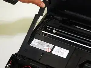
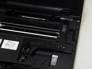
Rotate the arm approximately 45 degrees to remove the bottom portion from the device.
-
-
-
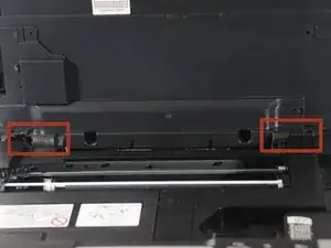
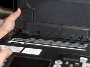
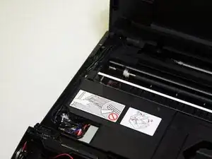
Slide the unit either to the left or right and push it away from the device.
-
Once one hinge is separated from the device, begin to remove the other hinge.
-
Gently place the unit on the work surface.
-
-
-
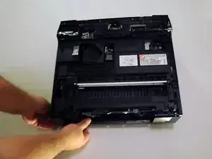
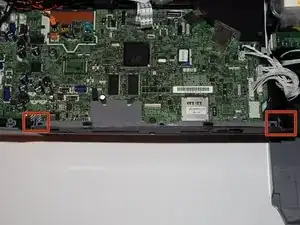
From the back of the device, use the exposed portion of the panel and gently begin to remove the panel away from the device.
-
-
-
Use the exposed portion of the panel to begin to lift the panel away from the back of the device.
-
-
-
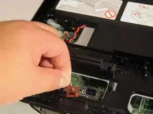
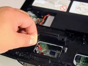
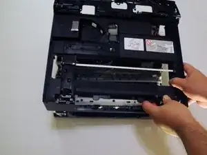
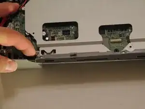
Gently pull the data cable out of the motherboard.
-
Slide the cable out of the slots to remove it from the device.
-
Once separated, place the unit and ground screw in a safe area of the workspace until they are needed for re-assembly.
-
-
-
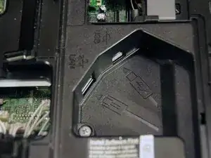
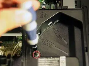
Locate and remove the screw near the USB and ethernet ports.
-
Unscrew the 8mm screw at the center of the device.
-
-
-
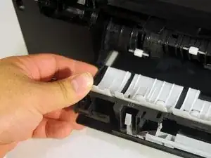
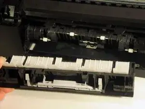
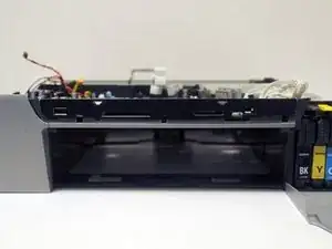
Gently push the upper-left tab of the paper jam clear cover and separate the hinged portion of the cover from the rest of the device.
-
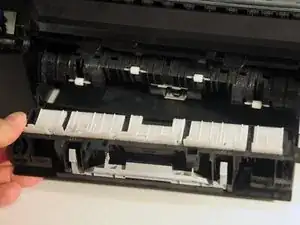
Once one side of free, slide the other side away from the device.
-
Pull the cover away from the device.
-
-
-
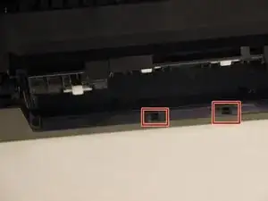
Using a spudger, loosen the two clipped portions of the cover located at the back-center of the device.
-
Once the clips are free the rest of the cover can be lifted up and away from the device.
-
-
-
Push the left and right clipped portion of the front port cover away from the device.
-
Pull the cover away from the device.
-
-
-
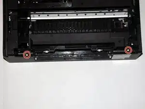
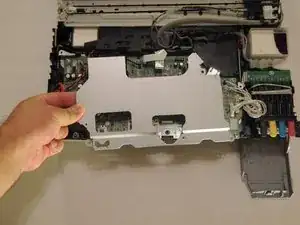
Unscrew the three 8.3mm screws from the motherboard cover.
-
Lift the motherboard cover away from the device.
-
-
-
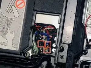
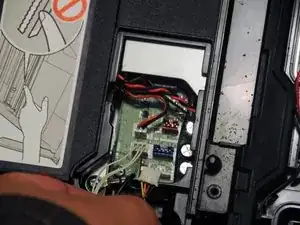
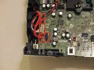
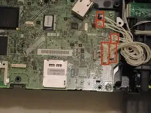
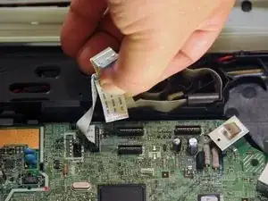
Lable the white cable before removal.
-
Add a label to the port where the white power cable is inserted.
-
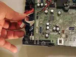
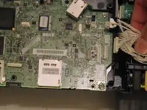
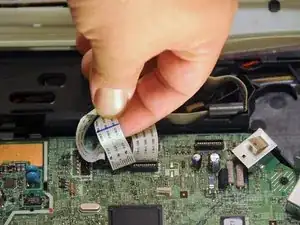
Remove the rear black and white power cables.
-
-
-
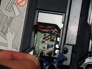
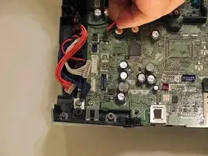
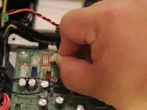
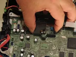
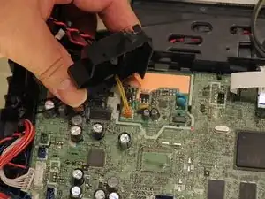
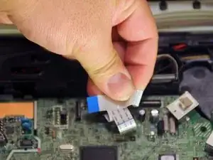
Squeeze the clips of the cover protecting the orange power cable.
-
Lift the cover away from the motherboard and set it aside.
-
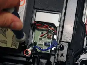
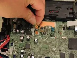
Gently lift the orange power cable away from the motherboard.
-
-
-
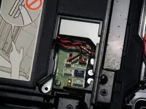
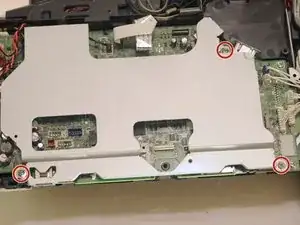
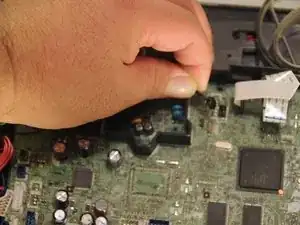
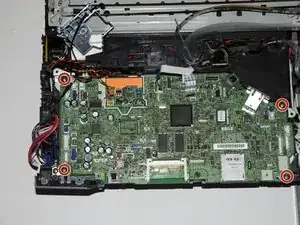
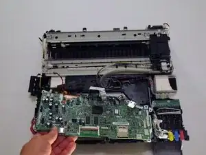
Using a screwdriver, remove the four 12.1 mm screws.
-
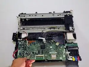
Lift the motherboard away from the rest of the device.
-

To reassemble your device, follow these instructions in reverse order.
2 comments
How Did you program the new mainboard with serial # and other info???
Also works for DCP J715W and probably others since they all look alike.
(Don’t try to pry open the front panels on the DCP J715W. It’s just for decorative purpose, and I broke the one-way plastic clips trying to remove them. The rule seems to be “If you don’t see a screw to remove a part, it’s that you didn’t find it yet” (All meaningful “one-way plastic clips” I found were easily accessible))