Introduction

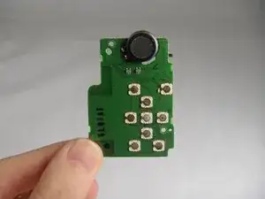
If your camera's function keys are nonresponsive, you may need to replace the function key motherboard. After removing the back cover and the LCD screen, you will be able to replace the function key motherboard yourself.

  1. mItqjh2IpZFdYgG1
    mItqjh2IpZFdYgG1
    fRbCCFgV1khva1Yq
    • Turn off the camera.

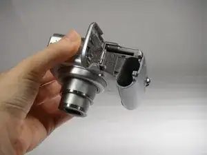
    • Turn the camera upside-down and press the tab to release the battery cover. Remove the batteries.

  2. PCKUMCrADGUNOIOq
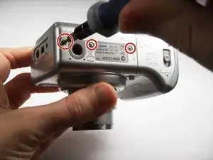
    • Turn the camera upside down to view the "Card/Batt. Open" Cover.

    • Use a Phillips head #000 screwdriver to remove the three (3) 4.0 mm screws.

  3. FrARZrsAitm3USOj
    • Open "Card/Batt. Open" Cover.

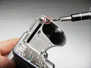
    • Remove the one (1) 5.0 mm screw with the Phillips head #000 screwdriver.

  4. C32Ry1FsUJOoPnlq
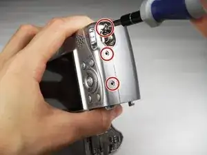
    • Turn the camera to the right side of the LCD screen.

    • Remove the three (3) 4.0 mm screws with the Phillips head #000 screwdriver.

  5. Gi2KgRmMsEIgrTfC
    Gi2KgRmMsEIgrTfC
    GqppF2J2LTxaxInG
    ewnOLvKLC2ltGXUl
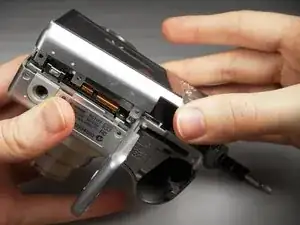
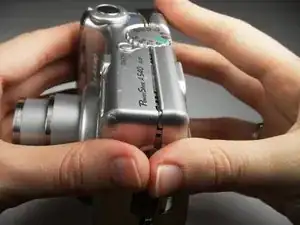
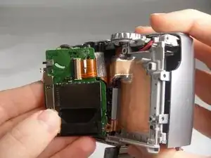
    • Gently remove the back cover.

    • Start at the bottom at the corner of the "Card/Batt. Open" Cover.

    • Then move onto the other edges and the top.

    • It may be tight at the top!

  6. xeyVV5WuUAxOJZSm
    xeyVV5WuUAxOJZSm
    4m1aDR5YpDtFkexG
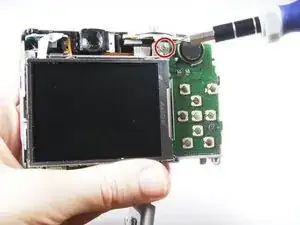
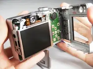
    • Turn the camera to view the back.

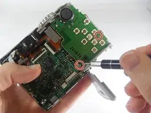
    • Remove the one (1) 3.0 mm screw on the top right corner of the screen.

    • There is a small metal bar that rests on this frame. Keep it with the screws that have been removed from the camera.

  7. EjIpi66XlCNTCYLY
    EjIpi66XlCNTCYLY
    6wxCjkMKPXlb24ji
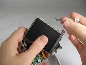
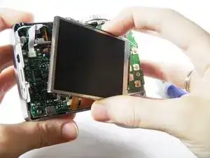
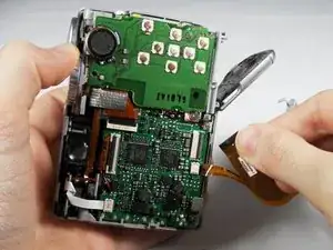
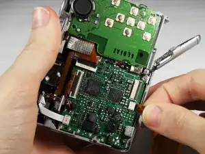
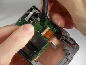
    • Lift the LCD Screen off of the back to view the attached ribbon cables.

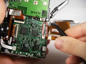
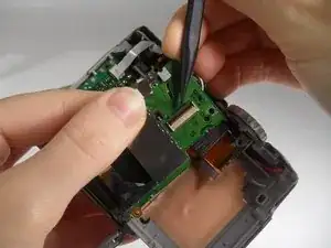
    • Use tweezers to flip the black bar up.

  8. dIC2hInQINxhkFwx
    dIC2hInQINxhkFwx
    54YsFg1Me3OgKGVE
    1VuUai6C4G55QMut
    • Gently pull the big ribbon out.

    • Gently pull the small ribbon out.

    • The small ribbon does not have a bar like the big ribbon.

  9. lWA1nSu6RXIjsIQO
    lWA1nSu6RXIjsIQO
    xmLPaWD1vPAMnktC
    • Remove the two (2) 3.0 mm screws with the Phillips head #000 screwdriver.

  10. rirkUmMqVBjQS5Dl
    rirkUmMqVBjQS5Dl
    cimFIsXL1lxlvTD2
    • Remove the orange ribbon from the clamp by using a Spudger to push the bar up.

  11. FeuDkfgg6cQjfLL6
    • Remove the Function Key Motherboard and replace.

    • There is another metal bar that comes off of the SD Card reader when screws are removed.

Conclusion

To reassemble your device, follow these instructions in reverse order.

Cooper Hale

Member since: 22/03/15

532 Reputation

0 comments