Introduction
If your HP 15-da0012dx Laptop trackpad or keyboard is not inputting correct clicks, mouse movements, or keyboard inputs, follow this guide to replace the keyboard and track-pad panel.
A keyboard and track-pad should provide inputs to put information into your computer. A faulty keyboard and track-pad will allow only some inputs or even no inputs at all. Before taking apart your laptop it is smart to restart and try each the track-pad and keyboard a few times to confirm faulty hardware.
Before following this guide be sure to ground yourself by touching a metal object such as your computer case, or by using an anti-static wrist band.
-
-
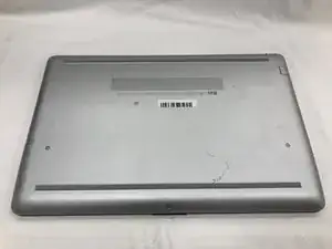
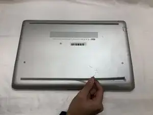
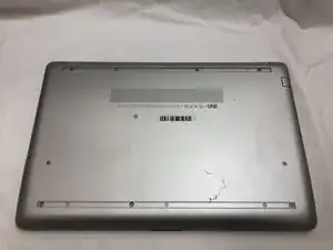
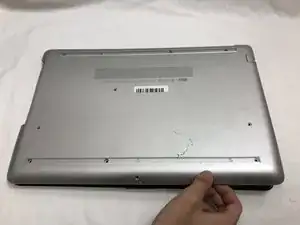
Turn your laptop over so that the Laptop Identification Tag on the underside of the laptop faces the ceiling.
-
-
-
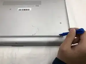
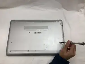
Using the plastic opening tools, peel back the plastic feet from the underside of the laptop.
-
-
-
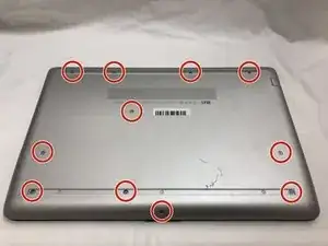
Using a Phillips #1 screwdriver, remove the eleven 9.0 mm screws holding the back cover in place.
-
-
-
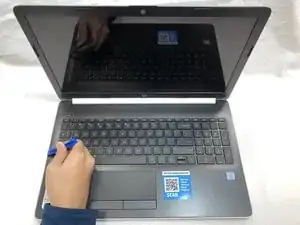
Flip the computer over and open the screen.
-
Start from a corner and run the plastic opening tools along the edge of the back cover.
-
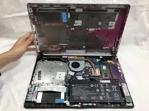
After the cover has been completely loosened around the entire perimeter, close the screen and flip the computer over.
-
Gently pry back the cover starting from the middle, bottom edge.
-
-
-
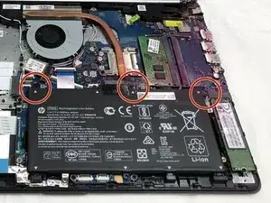
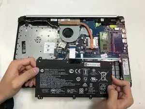
Using the Phillips #1 screwdriver, remove the three 8.0 mm screws holding the battery in place.
-
-
-
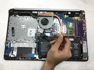
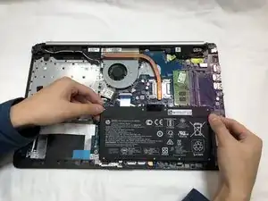
Remove the battery by tilting the top of the battery towards you and pulling the battery away from the mounting tabs.
-
-
-
Spread the retention clips on either side of the RAM module outward until you hear a click sound.
-
-
-
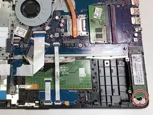
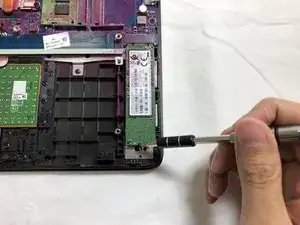
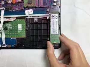
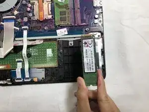
Using the Phillips #1 screwdriver, remove the single 3.0 mm screw holding the SSD module in place.
-
-
-
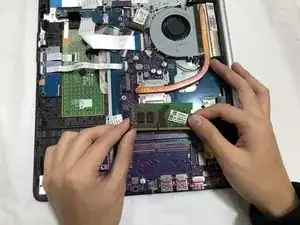
Using the Phillips #1 Screwdriver, remove the single 3.0 mm screw holding the wifi card and gently pull the wifi card away.
-
-
-
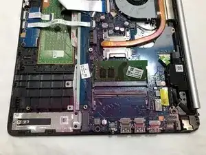
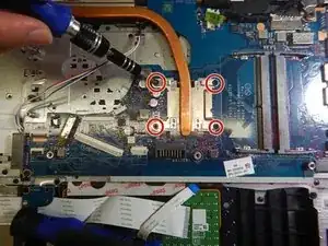
Using the Phillips #1 Screwdriver, remove the four 3.0 mm screws holding the heat sink in place.
-
Gently pull the heat sink out of the laptop.
-
-
-
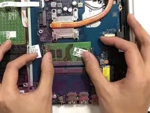
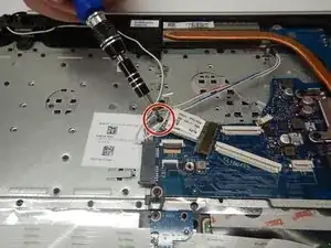
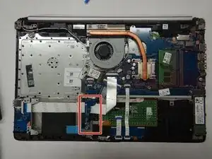
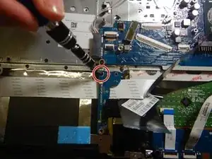
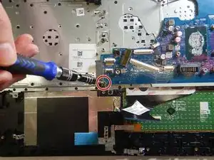
Using the Phillips #1 screwdriver, remove the single 3.0 mm screw holding the small circuit board.
-
Gently remove the small circuit board.
-
-
-
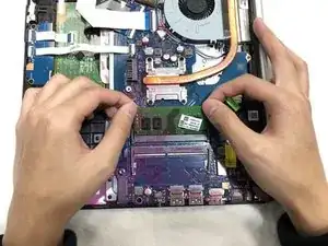
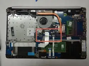
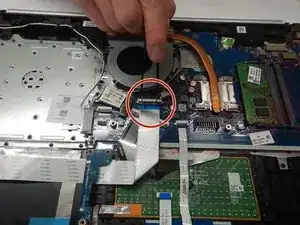
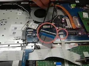
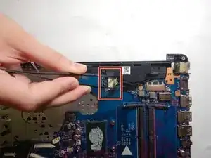
Using the metal tweezers, disconnect the ribbon cables from the motherboard .
-
First remove the USB board cable followed by the keyboard and touchpad cables.
-
-
-
Using the Phillips #1 screwdriver, remove the single 3.0 mm screw holding the USB card in place.
-
Gently remove the USB card from the laptop.
-
-
-
Remove the speaker cable from the cable holder.
-
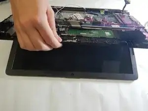
Tilt the bottom of the laptop up 30 degrees to move the monitor holders up to allow access to the rest of the laptop, and then return the laptop to its original state.
-
-
-
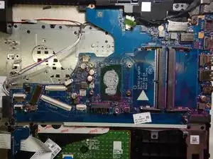
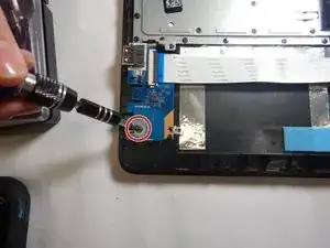
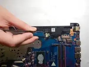
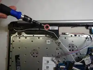
Using the Phillips #1 Screwdriver, remove the 3 mm screw from the motherboard.
-
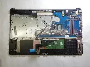
Carefully remove the motherboard.
-
-
-
Use the Phillips #1 screwdriver to remove the 3mm screws holding the speakers in place.
-
Carefully lift the speakers out of the laptop.
-
-
-
Use tweezers to remove the power connector from the laptop.
-
Carefully remove the power jack.
-
-
-
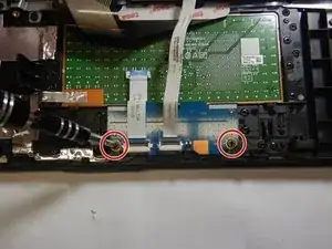
Use the Phillips #1 screwdriver to remove the two 3 mm screws holding the mouse buttons board down.
-
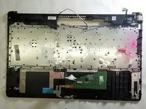
Carefully remove the mouse buttons board.
-
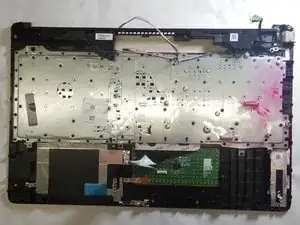
To reassemble your device, follow these instructions in reverse order.

One comment
You omitted the step to remove the screen assem and also the fan