Introduction

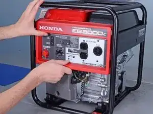
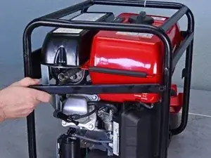
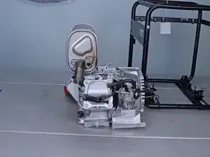
This guide demonstrates how to remove or replace the rotor and stator assembly on your Honda EB3000CK2A 3000 Watt Generator. The rotor and stator are removed as one unit. If you need to replace the rotor or stator individually, consult the generator’s service manual.

This is a very involved procedure and requires major disassembly. If you encounter problems during the process, consult the official Honda service guides.

You will need a universal puller with a metric collar set in order to pull the rotor off. If the bolts included do not fit correctly in the threaded holes of the rotor, you can use the 61 mm-long bolts removed in Step 41 of this guide.

The rotor is heavily bolted onto a free-spinning shaft. An impact wrench may be able to loosen the bolt. You may also need a strap wrench to hold the rotor steady.

Drain the fuel from the fuel tank before you begin this procedure. Any fuel remaining in the tank will spill out. Be ready to contain any spillage.

There are a large number of fasteners on the generator that must be removed for this repair. In order to keep them all organized and accessible, replace them in/on the same bolt hole or stud they were removed from as you work through the guide.

Drain all fuel from the device before beginning this guide.

Some photos may show minor visual inconsistencies relative to this guide. These inconsistencies do not affect the repair procedure.

  1. LJprNZigAHiOTmKi
    LJprNZigAHiOTmKi
    2dPCI5qOTUqYFMN2
    • Before you begin, disconnect the spark plug connector from the spark plug.

  2. gJLDtXqx5bXaNJqa
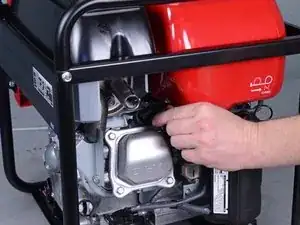
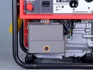
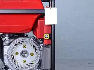
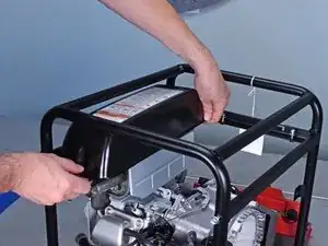
    • Use a 10 mm socket to remove the nut securing the top of the cyclo converter cover.

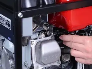
    • Use a 10 mm socket to remove the bolt securing the bottom of the cyclo converter cover.

  3. BZKAfXntvlEFCFAO
    BZKAfXntvlEFCFAO
    iyKjBjJp6WCk13k2
    n2Y5qLRrEZTRSubJ
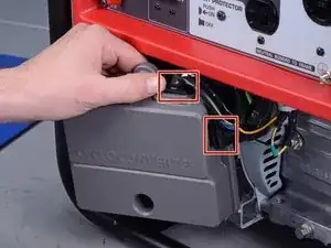
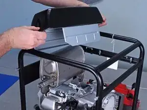
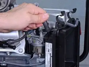
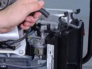
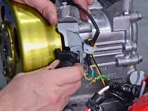
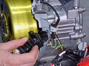
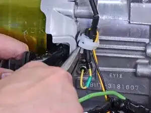
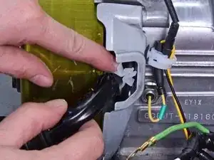
    • Un-slot the two black rubber cable grommets from the top and right edge of the plastic cover.

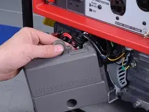
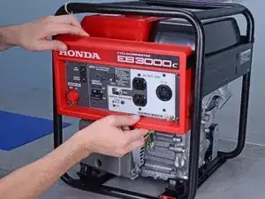
    • Remove the cyclo converter cover.

  4. uXyDfpOY4ADlr4AQ
    uXyDfpOY4ADlr4AQ
    iZMtimUhIKkGbrlr
    heFTDxvvP2KXC2lt
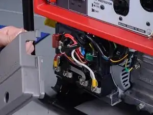
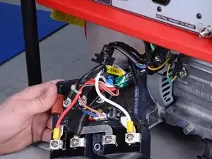
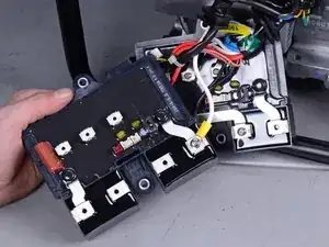
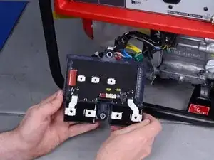
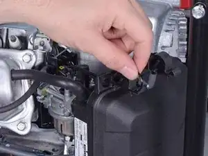
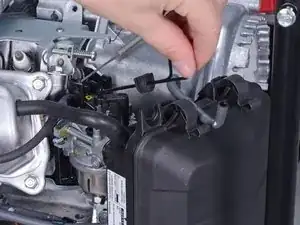
    • Pull the cyclo converter panel off of its posts on the generator body so the screw terminals are easily accessible.

  5. KMjmWRREYOmHvbRP
    KMjmWRREYOmHvbRP
    TPHBmv2DTpHArofo
    Ix4GNpXlH2qKw3ND
    • Disconnect the two 2-pin and one 3-pin connectors from the panel.

    • Take note of which connector corresponds with each header for reassembly.

    • Reassembly tip: The connectors are keyed so they can not be plugged in with the wrong orientation.

  6. jeYCdWkFltfXjhaP
    • If you are replacing the cyclo converter panel, it can be helpful to transfer a cable from the old panel to the corresponding screw terminal on the replacement panel one at a time. This prevents potentially mixing up cables and screws and maintains OEM cable management.

    • The top three screws are M4 screws while the bottom four are M5 screws. Ensure you are using the correct screw for each terminal during reassembly.

  7. YJtlnAUR5GFxVoRd
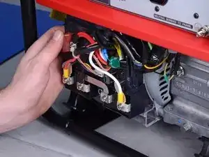
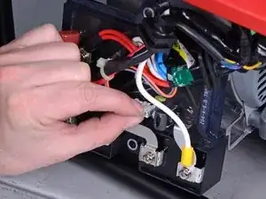
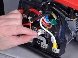
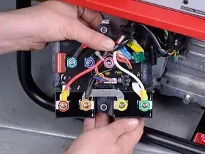
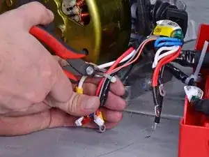
    • Use a Phillips #2 screwdriver to remove the seven 10 mm screws from the terminals on the cyclo converter panel. The wire that corresponds with each terminal is listed below:

    • Red cable

    • Double Black cable

    • No cable

    • White Cable

    • Double Red cable

    • Double White cable

    • Double Blue cable

  8. MyMeYSXsVHEq54PG
    MyMeYSXsVHEq54PG
    g6S2bIWGrUf2YkSr
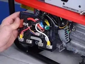
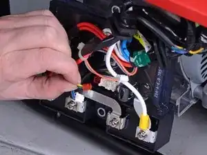
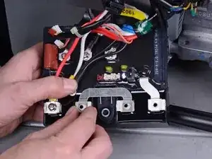
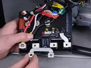
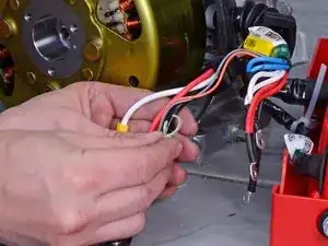
    • Remove the terminal connecting bar from the panel once the corresponding terminals are unscrewed.

    • During reassembly, ensure the bar is in the correct orientation and lies under the crimp connector on the double black cable.

  9. qconocxHGad5jXKe
    • Remove the cyclo converter unit.

  10. BGJqWDndTBCDSJKf
    BGJqWDndTBCDSJKf
    qIP1X2OIgqYcYQla
    Zkogj6VdBJ6uEwPd
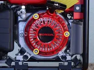
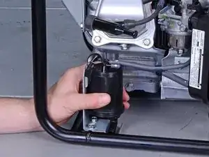
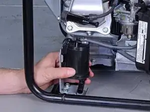
    • Use a 10 mm socket to remove the three 12 mm-long bolts securing the recoil starter assembly.

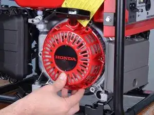
    • Remove the recoil starter assembly.

  11. QEUFkFIlN3xieAFs
    QEUFkFIlN3xieAFs
    t46wWLQwnhJJtX6G
    lqHJHtSOEpGOb5a3
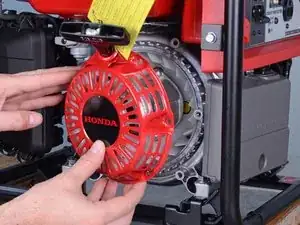
    • Use a 10 mm socket to remove the two 20 mm-long bolts securing the recoil starter pulley.

    • Remove the recoil starter pulley.

  12. iFYn121g342PodZt
    iFYn121g342PodZt
    yFG3dbUSTwUZPtnX
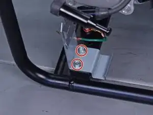
    • Use a 10 mm socket to remove the two 20 mm-long bolts securing the sides of the control box case.

  13. YgunJqhVixEgakYy
    YgunJqhVixEgakYy
    KScHRQevNhMqEWsb
    LlIUFA4ZPLjSJAKZ
    • Remove the control box from the generator frame and tilt it downwards.

    • Do not attempt to completely remove the control box as it is still wired to the generator.

  14. YRhErNZx3v6Wlce4
    YRhErNZx3v6Wlce4
    dMuAImJF3YngTcLH
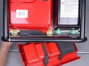
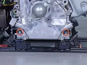
    • Use a 10 mm socket to remove the five bolts securing the muffler protector and the fuel tank to the frame:

    • Two 25 mm-long bolts

    • Three 15 mm-long bolts

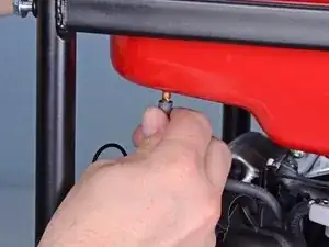
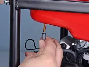
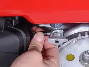
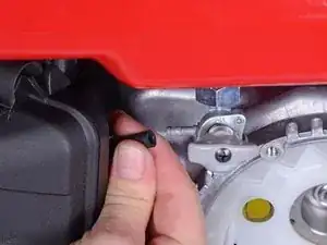
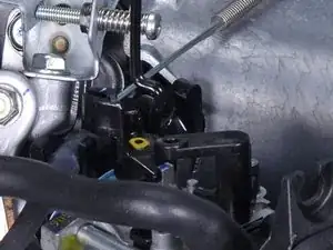
    • Use a pair of pliers to remove the lock pin and clutch joint securing the fuel tank to the frame.

  15. yJJFenNxEuy6ChEA
    yJJFenNxEuy6ChEA
    XhuvRJhDgXMXawCB
    OWIhOUZdeIFM4cKv
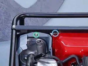
    • Use a 10 mm socket to remove the two 20 mm-long bolts securing the fuel tank bar to the rest of the frame.

    • Remove the fuel tank bar.

  16. p2DlsBbMUiDbbwlo
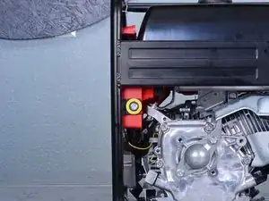
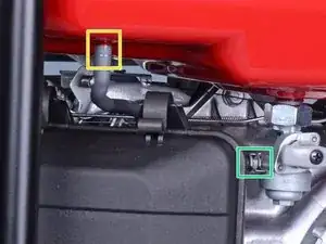
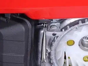
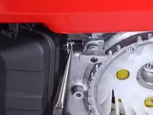
    • Identify these two tubes and their tube clamps:

    • The tube connected to the bottom of the fuel tank

    • The tube connected to the petcock assembly

  17. J1wUGKBZOFOHRBIb
    J1wUGKBZOFOHRBIb
    4pikypAlyOYcd5md
    • Use a pair of pliers to squeeze and shift the first tube clamp down the fuel tank tube.

  18. QivgggICPpybwNUV
    QivgggICPpybwNUV
    nyoajkLZRad3WYEK
    • Disconnect the tube from the fuel tank.

    • Residual fuel may leak when you disconnect this tube. Be ready to catch any spillage.

  19. QbPJd5NkINXBiktU
    QbPJd5NkINXBiktU
    ETUmcBkM64BqVYRA
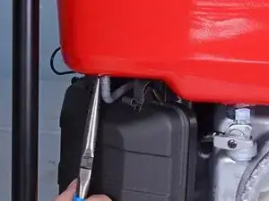
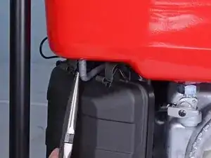
    • Use a pair of pliers to squeeze and shift the second tube clamp left and away from the petcock assembly.

  20. dgXvOKRB5broEdAY
    dgXvOKRB5broEdAY
    II3UTMepuJdpNKT1
    • Disconnect the tube from the petcock assembly.

  21. cLPQkv3LDWyTG3uL
    cLPQkv3LDWyTG3uL
    iKJ63LAbl6f4KlGr
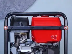
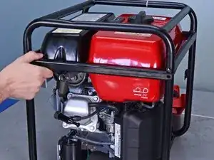
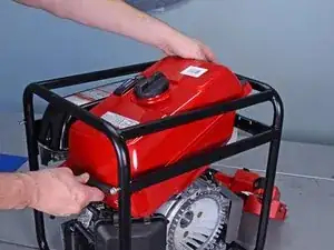
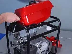
    • Gently lift one side of the tank and slip it out of the generator frame.

    • Remove the fuel tank.

  22. AcmSjb1GGOYGL5pB
    AcmSjb1GGOYGL5pB
    LgHfrBe3BKYWVMe3
    • Remove the muffler protector.

  23. U1f3BQnfk4qTmRRs
    U1f3BQnfk4qTmRRs
    1V2OV5ycno6vejTF
    • Lift the choke rod off of the air cleaner housing.

  24. aSgNQpxIhwfUZbLH
    aSgNQpxIhwfUZbLH
    1EEXvKGJiDKeJ1dE
    PfJJYptvAobTOBqU
    • Continue lifting the choke rod until it's free from the generator.

    • Remove the choke rod.

  25. 54e5UsHWNi2XxvyI
    54e5UsHWNi2XxvyI
    NKX1OpeKYtybpGxX
    NymZQS2RmHFOLTOb
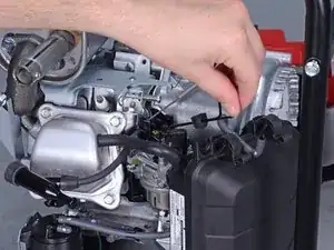
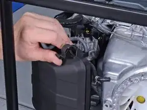
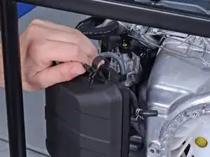
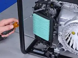
    • Unclip the two clips on top of the air cleaner housing.

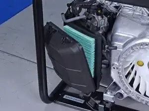
    • Tilt the air cleaner cover down slightly.

  26. U23Tq3sxv2awvKVx
    U23Tq3sxv2awvKVx
    ZrELcKhM6vnZWCFH
    • Remove the air cleaner cover.

  27. qeOUer3QfZaTF4xL
    qeOUer3QfZaTF4xL
    eGqCe5sfc3XbQ2Na
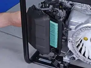
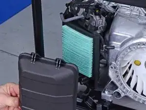
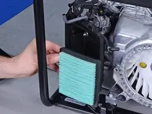
    • Use a flathead screwdriver or a pick to remove the air cleaner element from the air cleaner housing.

  28. whVuTBjhssWJWwDl
    whVuTBjhssWJWwDl
    1LYuDXNOOtk2BVYb
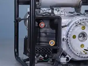
    • Use a 10 mm socket to remove the two nuts from the inside of the air cleaner housing.

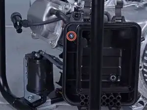
    • Use a 10 mm socket to remove the 20 mm-long bolt from the inside of the air cleaner housing.

    • During reassembly, tighten these fasteners to 7 lb-ft (10 N-m) of torque.

  29. wJKvWBxP2njuvXB4
    wJKvWBxP2njuvXB4
    W23dacjI1sSFGRuB
    • Pull up and disconnect the breather tube from the top of the air cleaner housing.

  30. yrOQtTEK2QDZGsyD
    yrOQtTEK2QDZGsyD
    olEQgCKX4K6LBx62
    XmABD645k4RqfJOE
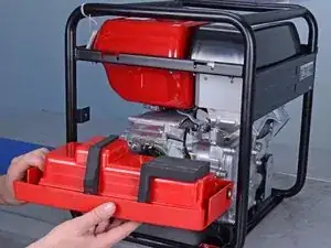
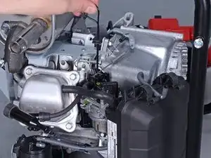
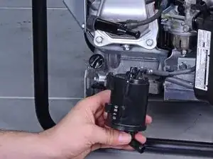
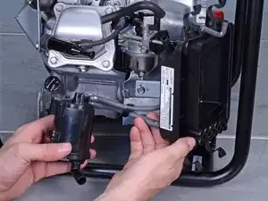
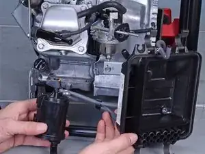
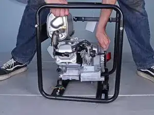
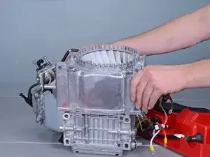
    • Lift up the canister assembly from its mounting rails to release it from the generator frame.

  31. ERxDuMbYlqN3OxhM
    ERxDuMbYlqN3OxhM
    aArSPdtwgsZFEREi
    • Remove the air cleaner and canister assembly.

  32. XUZHtRYsL1IHtFBl
    XUZHtRYsL1IHtFBl
    OMhBjIYgXw1msnm6
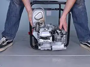
    • Use a 12 mm socket to remove the four nuts securing the motor assembly to the generator frame.

    • During reassembly, tighten these nuts to 25 ft-lb (34 N-m) of torque.

  33. ug6sJ5tMSPuPahAJ
    ug6sJ5tMSPuPahAJ
    yn3K1BhHlHV4Q2FO
    • Remove the ground ring terminal from its motor mount bolt.

  34. ihrKHigPTvYKHR64
    ihrKHigPTvYKHR64
    QiGIqix5E15saU2k
    Sl4EcNlLTk3bZbmu
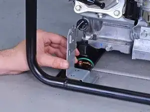
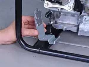
    • Use a 10 mm socket to remove the two 15 mm-long bolts securing the canister bracket.

    • Remove the canister bracket.

  35. QTdsJAkKXbxnNaEX
    QTdsJAkKXbxnNaEX
    X2GGvGkTd4Zxreok
    KL1S6HFnAnorEE3l
    • To prevent injury and damage to the device, we highly advise you to perform this step with another individual during reassembly.

    • Remove the motor assembly from the generator frame.

    • Try having one person lift the motor while another slides the frame out from under it.

  36. XVfhYUwOcBfL53Rj
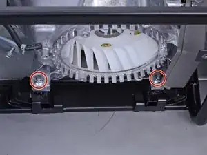
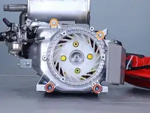
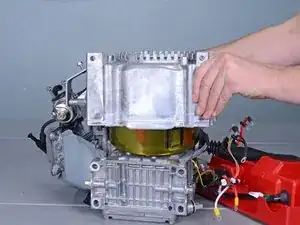
    • Use a 10 mm socket to remove the four bolts securing the fan housing:

    • Two 40 mm-long bolts

    • Two 30 mm-long bolts

    • During reassembly, tighten these bolts to 7 ft-lb (10 N-m) of torque.

  37. YNMKRHfUpgbYbm3s
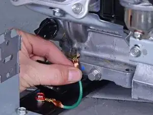
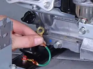
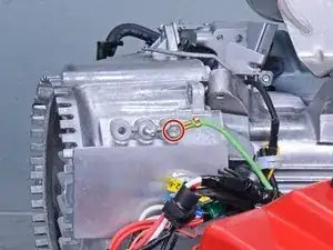
    • Use a 10 mm socket to remove the 12 mm-long bolt securing the ground cable to the fan housing.

  38. BdYpamHLkQON4PhI
    BdYpamHLkQON4PhI
    GaKEJiYwqlvG13wV
    WfipJHTWS16kCVeS
    • Lift up and remove the fan housing.

  39. hYlo45yAnpFEB4XC
    hYlo45yAnpFEB4XC
    FbsqWn2KugR6bDQq
    • Remove the cooling fan.

  40. QAWaBnqc5SRKAAtT
    QAWaBnqc5SRKAAtT
    PcyqJu5t6NZcCdYI
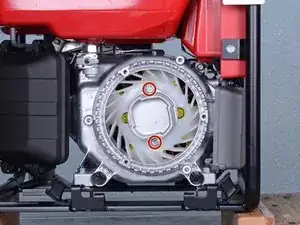
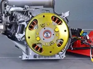
    • Use a 19 mm socket with an impact driver to remove the rotor nut from the generator assembly.

    • During reassembly, tighten this nut to 53 ft-lb (74 N-m) of torque.

    • If you are not able to tighten the nut without the rotor moving, use a strap wrench to hold the rotor in place while refastening the nut.

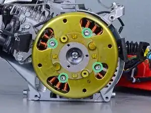
    • Use a 5 mm hex driver to remove the four 61 mm-long bolts from the generator assembly.

    • During reassembly, tighten these bolts to 8 ft-lb (11 N-m) of torque.

  41. HlWPux1x2pBUCpiS
    HlWPux1x2pBUCpiS
    r3reFVvFES1Pjp6g
    i562KRGTHDnCrxVL
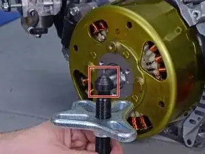
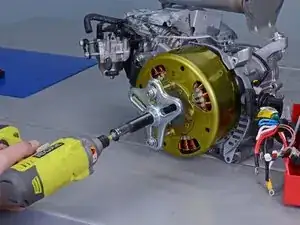
    • Ensure the proper pointed tip is fastened to the center of your universal puller.

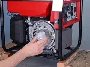
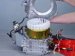
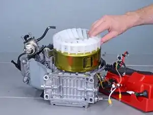
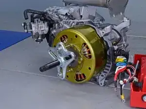
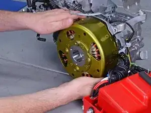
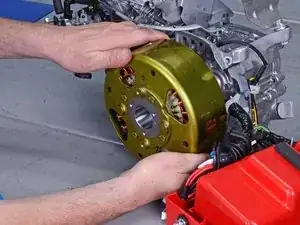
    • Affix the universal puller to the face of the rotor.

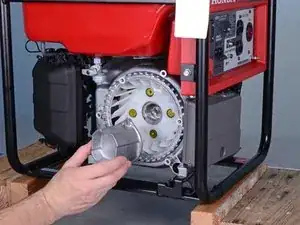
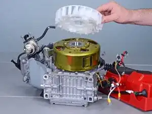
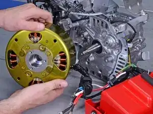
    • Use an impact driver to pull the rotor and stator assembly from the crankshaft.

  42. dLnft1i16TUjSB5W
    dLnft1i16TUjSB5W
    AORBnDBKdEUVJB63
    • Cut and remove the zip tie securing the stator wires to the rest of the harness.

  43. MkbkDc44BTDGAPWY
    MkbkDc44BTDGAPWY
    LiN4TMeAgHZ3mWnL
    goPZADjqelsQ5Epf
    • Unseat the stator wiring harness grommet from the rotor side plate.

  44. Rs4abPKpXXLP1PBa
    Rs4abPKpXXLP1PBa
    LkTvsVx2AVhGtiF2
    jYdNHDnQOlUQ6FOC
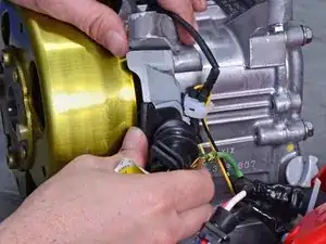
    • Use a pair of pliers to squeeze and release the wire harness clip from the rotor side plate.

  45. ajHBDmTGrrFTli2Y
    ajHBDmTGrrFTli2Y
    CA21SMiD5YFI6OB4
    x5AwA4NdJlwEDgjs
    • Remove the rotor and stator assembly.

  46. tFHlXgTvHp5sqckl
    tFHlXgTvHp5sqckl
    UIJKVpYTcECeMbXD
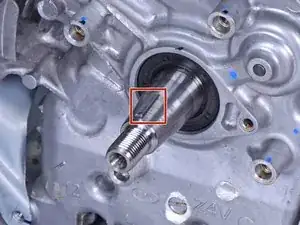
    • Before you install the new rotor and stator assembly, ensure the axle key is properly installed.

    • Be sure to route the stator wiring harness in the correct orientation, as shown in the second photo.

Conclusion

To reassemble your device, follow these instructions in reverse order.

Tarun Thiruma

Member since: 20/11/19

33509 Reputation

2 comments

Question, The rotor is it magnetic?

bk2571 -

The rotor flywhell is it magetic?

bk2571 -