Introduction

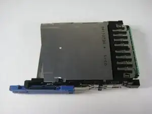
This repair guide will aid you in taking apart your IBM ThinkPad T41 laptop to reach and replace its expansion slot.

  1. BvJXL3bwuZDlJgxo
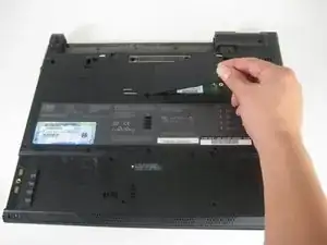
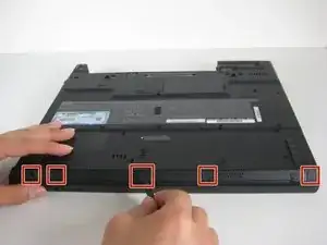
    • Close the screen and turn the closed laptop over.

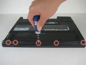
    • Remove all 17 screws on the bottom of the computer.

    • The multiple colors (turquoise, red, blue, orange, yellow, and purple) are for organizational purposes, indicating different screws.

    • The yellow marker at the rear denotes the UltraBay device retaining screw. This screw is optional as the UltraBay mechanism will hold the drive or battery in place anyway. The yellow marker at the front denotes the hard disk caddy retaining screw.

    You need to remove the battery, hard drive, and UltraDrive before starting step 1.

    cak -

  2. qCjiHHxgecxSVpZe
    • Remove the extra RAM cover, by lifting where the screw was and pulling out.

    If there's extra RAM under the cover, remove it by spreading the retaining clips.

    cak -

  3. oof2K5i4IltsabVQ
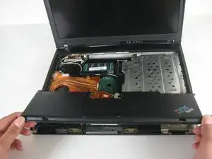
    • Turn the laptop right side up and open the screen.

    • Lift the keyboard, using a spudger at the seam between the keyboard and trackpad.

    • Careful of the ribbon cable underneath, which may tear if the keyboard is lifted too vigorously.

  4. rxeSVXlW1fRbYBjN
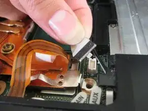
    • Unplug the keyboard’s ribbon cable, by lifting up the edges of the plug.

    • Remove the keyboard.

  5. vWKUVmXtCYvRKrqN
    • Close the laptop and turn it over.

    • Remove the five plastic stickers covering the screws on the front edge of the case.

    • In order to reuse the stickers, remove them carefully.

  6. XPViub3dGAelMXSB
    • Unscrew the five screws that were hidden by the stickers.

  7. DSRVDYxVfBawcKtG
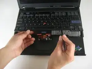
    • Turn the computer right side up and open the screen.

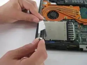
    • Lift the trackpad assembly by placing hands on both edges and then pull towards you till it is free of the case.

    • Be careful of the ribbon cable underneath. It may tear if the trackpad is pulled too vigorously.

  8. hEEtVdnyLURUI5D3
    • Unplug the trackpad’s ribbon cable by pulling on the white plastic tab.

  9. TIn4CeMxbvKFWQ4P
    • Lift the speakers out by starting with the left end and then unsnake the wires.

  10. 6RwWDdO6iToi16TI
    • Unplug the wires from the motherboard.

  11. BQGTYYktYYoTUYsT
    • Remove the screw on the left hand side of the case, above the expansion slot.

  12. 3reSMyB2OklR3hwg
    3reSMyB2OklR3hwg
    6KxqPgtLhO5RN4fR
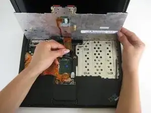
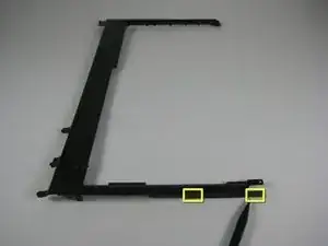
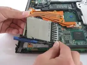
    • Lift the black plastic border by lifting on either side.

    • Once the sides are up, pull the border towards you and away from the screen.

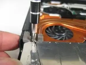
    • When lifting up, there are two pairs of plastic clips hooking into the fan grill. If you pull hard enough the border will come away, but it's better to push the clips with the spudger.

  13. kWE3TSYgwOKPNEnZ
    • Pull the sheet metal cover away from slot.

  14. 6cWlfwRUflEEJk2B
    • Lift out the expansion slot by starting at the entrance hole and pulling upward.

    • Note: Try wiggling the slot from side to side until it comes out all the way.

Conclusion

To reassemble your device, follow these instructions in reverse order.

Marissa Blustein

Member since: 16/04/10

492 Reputation

0 comments