Introduction
The LeapFrog LeapPad 32400 has a large front screen which may break or not function properly requiring it to be replaced.
In this guide you will be replacing the screen component for this device. To do this you will be working on both the front and internal components. Caution is to be used when pulling out the screen as it is quite easy to damage or break the outer covering.
Check the troubleshooting page for symptoms to make sure this guide is the best route: LeapFrog LeapPad #32400 Troubleshooting Page
-
-
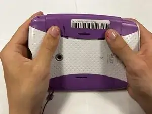
Turn the tablet so the back is facing up.
-
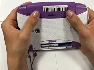
Remove the battery covers by sliding the covers towards the sides and away from the center of the device.
-
-
-
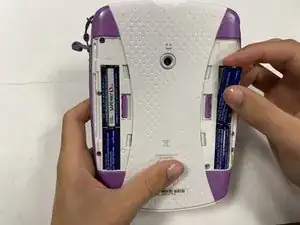
Take out the AA batteries from both battery compartments of the device.
-
Replace batteries as needed.
-
-
-
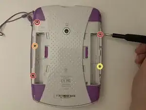
Remove three 7 mm screws using a Phillips #1 screwdriver.
-
Remove the single 6 mm screw using a Phillips #1 screwdriver.
-
Remove the single 10 mm screw using a Phillips #1 screwdriver.
-
-
-
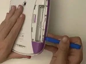
Use a small plastic opening tool to separate the colored front cover from the white rear cover of the device.
-
With one hand on the front cover and one hand on the rear cover, start from the bottom of the device and pull the pieces apart.
-
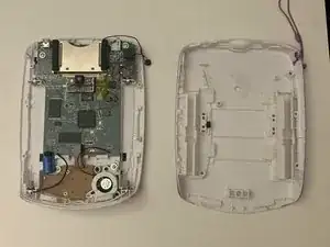
Once only the top edge remains connected, pull the rear cover backwards away from the front cover and upwards towards the top of the device. This should release the last remaining tabs holding the pieces front and rear cover together.
-
-
-
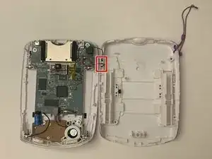
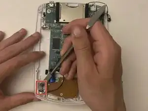
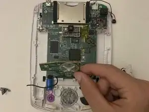
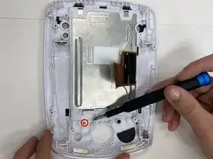
Separate the motherboard from the back side of the device by detaching the black and red wire connection from the back cover.
-
-
-
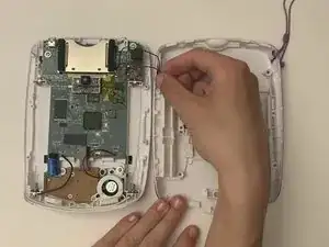
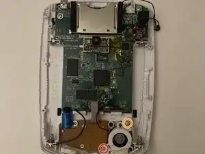
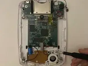
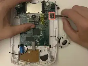
Remove the single 10 mm screw from the device using a Phillips #1 screwdriver.
-
Remove the single 7 mm screw from the device using a Phillips #1 screwdriver.
-
-
-
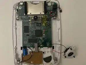
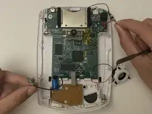
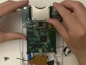
Gently lift the motherboard away from the back cover.
-
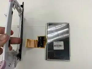
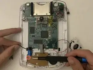
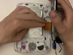
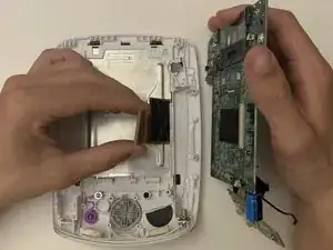
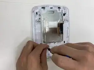
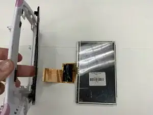
Peel back the tape on the display ribbon cable connector.
-
Gently pull on the display ribbon cable and it should easily slide out of the connecter.
-
-
-
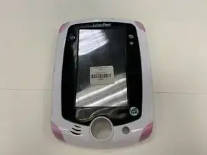
Flip the front cover over so the front screen is visible.
-
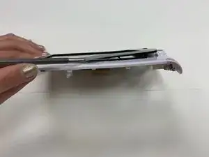
Using an iFixit opening tool, pry off the front black plastic border. Start from the bottom of the black border near the large center button, then make your way around.
-
Remove the screen from the device.
-


To reassemble your device, follow these instructions in reverse order.