Introduction

These speakers provide really good sound for their price, and it seems they accomplished that by using some cheap components.

It is a known issue that the Powered Speaker Select switch often goes bad, resulting in no audio out of one or both speakers. You should try using some contact cleaner first, but that can end up being just a temporary solution.

This fix makes your selection of Left or Right powered speaker permanent, but apart from the Aux in on the front, it is easy to just plug in your audio cables ‘backwards’ to have the audio come out of the correct speakers if you want to change your setup later.

If you are halfway competent with a soldering iron, this is a quick and easy fix. You’ll need to supply your own wire for this.

This is my first guide, and I didn’t plan on making it when I did the fix, so sorry about the lack of photos and details. Nothing would make me happier than for someone to take this info, fix their own speakers, and put together a better version of this guide while doing so.

  1. fWcAAqPKFsETjSNP
    • Turn off your powered speaker, Unplug it, and remove the 8 short Phillips head screws on the back.

    • Once removed, you can pull out the electronics from the casing pretty easily. A little care is required, as there is cabling connecting it to the speaker front, but there is enough slack that you don't need to worry about disconnecting for this fix.

    10 screws were present on my CR3 instead of 8. Worth noting the panel is only secured by the ones on the edges, and it took a hard tug on the cable to get it to come off.

    Jared Pittman -

  2. 6jfgrEgs4hOoIO1B
    6jfgrEgs4hOoIO1B
    CHVJLfpwXCjLSSSt
    Wvwj545KMGyOV2UB
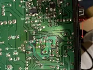
    • Arrange things so you have easy access to the underside of the circuit board, and the back panel to the right.

    • The contact points we need to work on are the bottom 4 in the cluster of 6 directly left of the switch on the back.

    • For the Powered speaker on the right, connect the top and bottom connections in that group of 4.

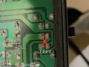
    • For the Powered speaker on the Left, cross the top and bottom connections in that group of 4.

  3. BOXlGalXwZGgLaY2
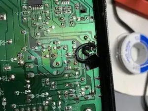
    • Solder two short wires to bridge the connections to hard wire your powered speaker to either Right or Left as desired. Finished result should look like the photo, (Right powered speaker selection) only cleaner, with no hastily added electrical tape shielding, because you are better at soldering than I am.

    • Do make sure your wires lay pretty flat to the board so it won't get in the way when you slide it back in to the speaker casing.

    Do you need to remove the switch before solder the wires, or you just did the solder work?

    Thank you

    Jose -

    I just performed this repair and you don’t need to remove the switch, but you need to make sure you don’t toggle the switch after soldering. In my case the switch snapped off so I can’t move it even if I wanted to.

    Sean Lee -

    Yeah, no need to remove the switch. When I first looked into repairing the speaker, I considered swapping out the switch for a new one, but it does not appear to be easy to remove without risking further damage.

    David Krug -

    I just performed the repair and didn't remove the switch. I also toggled the switch back and forth after putting everything back together, and it still works fine - the selector switch now does nothing, but it didn't seem to do anything harmful.

    Easy repair, although it might not be clear from the pictures exactly how small of a space you need to work in - hardest part of this repair was manipulating two tiny jumper wires to connect to the right points, without crossing wires or flowing too much solder onto the joints.

    Kevin Fleischman -

    If we could identify the switch, it could be replaced instead of bypassed.

    ehanneken -

    Just did this (my first time soldering too). I couldn't manage to solder a cable because of how small the nodes were, but I created a bridge (i.e. just soldered a line of iron between them) between the nodes labeled in this guide as the "powered speaker right" and it is working fine.

    Maxime Fournier -

    Just performed this repair on my CR3s. Saved me from throwing away perfectly good speakers due to the bad switch. Thank you!

    eklinc -

    Very usefull guide. They even appear to go louder .

    justin.stefan -

    Perfect user manuel! I already had this idea. I only didn’t no which connections I had to connect to each other. I used a string from an old telephone cable. That is a lot easier to use in the small space. A string from a UTP cable should also work I think.

    Robbert Landegent -

Conclusion

To reassemble your device, follow these instructions in reverse order.

David Krug

Member since: 01/01/20

472 Reputation

19 comments

You have saved my bacon in spending extraneous money on something so simple to fix. Thank you so much!!!

Quentin Little -

Just wanted to say thank you for creating this. I did my fix slightly different than how you outlined yours by just bridging the solder points in the parallel "right" configuration with bare stranded wire. A bit neater than doing it with larger loops of insulated wire....possibly a little more unsafe? but the strands aren't touching the circuit board that is insulated anyway so im fairly confident its fine. Speakers work great now

Mario Marin -

Thanks for the tip! I did this. It was way easier and seems to be working well. I would never have managed with loops of insulated wire. We are talking about just a few millimeters between each of those contact points!

Track Smart -

To add on to what Track Smart said, I also just bridged the solder points with stranded wire and it worked!

Nabeel Hussain -

Tight space to work on but worked perfectly. Thanks David

Mark Micallef -

Thanks for thisI Thoug I have to start over. Indeed a tight space to work with and i've been soldering since I was 14 (50 now). A magnifying glass light would be handy. Also, for me I had to really pull on the back as it was tough to pull out after I took out all screws, without really having something to grip on to.

bketchen -

I initially cocked it up and there was only sound but staticy and very low volume in which speaker was selected. So I think I got the polarities crossed. So I did it again. The left speaker is restored like it was, so i'm back to 0 (not negative results). So I believe, as per another youtube that we need to remove the switch which is the problematic issue. Apparently relatively easy to do and hopefully I can heat up the backside of the circuit board and removing the switch entirely without disrupting my jumper connections if you are following me.

Another wonder is, can we replace the faulty DPDT switch with a proper one? I have tons of them including small ones that the toggle will probably fit the initial hole. Just a thought, could be a crap shoot. But clearly, for me, the switch still in place creates the issue of sound in only one speaker.

cheers. Brad

bketchen -

I just picked a CR3 set up at the thrift store for $5 and the switch is missing, i put bare wire where the switch was and i can get both speakers working, so i know they both work, thanks for posting this, i'll give this a try

Adam -

I have multiple Mackie CR sets and they all exhibit the same problem, this is a great solution and really not that hard to solder. Thank you David and others!

Emile -

This article saved my sanity with a faulty switch. After soldering with insulated wires as you shared, I made a point to secure everything with hot-glue. Thank you so very much!

Vineet Gupta -

Same old Mackie crap. They've been using cheap pots and switches on their products for years. I've purchased several hundred of their mixers over the years for post production, and the pots and switches invariably go bad with little age. Pretty disappointing.

cameronproaudio -

Repaired!!! ✅ I just did solder bridges instead of wires, but I wouldn't recommend it. Ideally it would be easier to remove the switch, but it's just so hard to work in there....

alphaethree -

Thanks, this works very nicely! Also I want to setup a 4 speaker setup with these monitors, I have tried just hooking the 3 passive ones to the powered speaker, but the problem is that one of the speakers is on the wrong channel, It is on the passive speaker left channel but I want to connect it so It's on the powered speakers channel on the right. I looked inside the powered speaker but there are 2 sets of wires - 2 going to the subwoofer and 2 going to the tweeter and I can't figure out where I could be able to connect them. Do you have any Ideas how to make this work?

Atdsu -

An absolute life saver. Thank you David for taking the time to post this article. Good man. My Mackie's are now back to life. I do still really like the sound of these CR3's on my desktop, despite Mackie's cheap component choices.

Al Cain -

Was about to toss mine after a new 3.5mm : RCA cable did not fix the problem, came across this guide ('not working' pre-appending to a search for 'cr3 speakers' clued me in to this being a common issue) and gave this a try. Success! I did it in about 10 minutes with a 15W iron and a hacky hacky solder bridge. Will use actual wire if that fails. Mercifully I don't tend to run these very loud so hopefully the other janky components hang in there.

Some Eric Guy -

What kind of wire should one use for something like this? Any tips for soldering the wire to the board?

gamesthatexist -

Thank you so much, this was bugging so much me for a year, mine were even broken to the point that none of the speakers would play sound. I'd like to add to pull out the electronics it is easiest to hold the speaker case with one hand an then pull out the board in the back by grabbing it inside the ventilation shaft (took me some time to realize this). Also I never soldered anything in my life before and just bought a soldering iron in hopes of being able to fix my speakers. After some texting with a friend who is very experienced, I decided go for 305°C and instead of using cables I'd bridge it directly. Practiced two or three times with an old broken HDD I had around and then went for the real deal. Because I was so nervous first I accidentally soldered the wrong parts but was able to remove it with a soldering pump. First try everything worked out and it's fixed, so I would rank this as medium difficulty for a total beginner.

mincedirl -

Stavo da ore a cercare di capire, poi cerco su internet e trovo la tua guida. Grazie mille

DAVINCI Official -

Thank you! I had this problem for some time and got worried thinking that their time was coming, but it was as simple as soldering 2 wires and voila! Thank you thank you thank you!

Daniel Ponte Miserendino -