Introduction

The cameras of the Atrix HD are protected by the housing of the phone, but they can be damaged by exposure to moisture, impact, or scratches. If your photo quality is suffering it may be time to replace the affected camera. With just two tools, you can be back to taking high-quality photos in no time.

  1. cXWgsirAVfTu1WNP
    cXWgsirAVfTu1WNP
    vsInsB5mxJDp5GpB
    qjPwTKq3jfmfrAbv
    • Before disassembling the phone, remove the SIM card and the MICRO-SD card, if equipped.

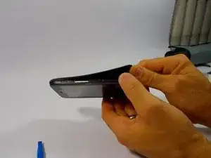
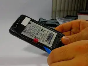
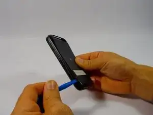
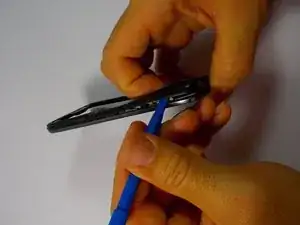
    • Begin taking apart the device by prying apart the back cover from the assembly using the plastic opening tool.

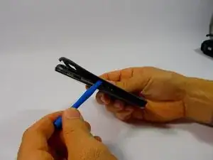
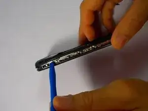
    • Continue working around the edge of the phone using the plastic opening tool.

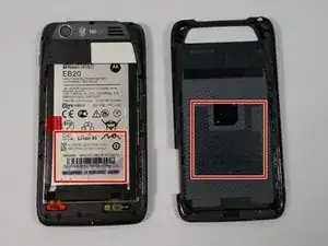
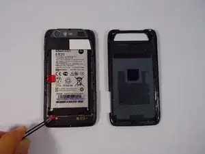
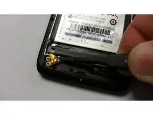
    • When all the edges have been lifted apart, use your hands or plastic opening tool to peel the back plate from the battery. There are small adhesive strips between the back cover and the battery, so take care not to crack the back cover while prying open.

  2. U2ekxIWqGNn4KiVT
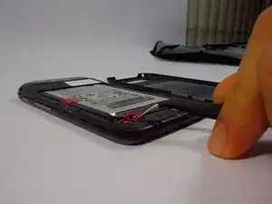
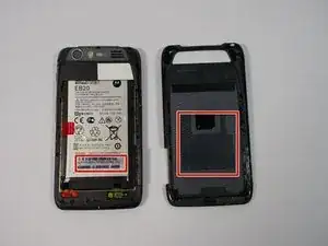
    • The adhesive strips are shown in the orange boxes. Be sure not to use too much force to pull off the back cover, or you may risk snapping the back cover.

  3. EOXAuN5TUXtwfQii
    EOXAuN5TUXtwfQii
    ZFmhUqFmmptbnLgP
    PtxbaIUQfKRyiIwF
    • Remove the red rubber screw cover with a pair of tweezers

  4. RTfFsTsYLsygrlMd
    RTfFsTsYLsygrlMd
    TumNY1QiJowovoWP
    • Use the T-5 Torx bit to remove the two silver 3.3 mm screws with integrated washers.

  5. XAgIZCYjOUEvM1VF
    • Lift the battery leads to the upward position. The ribbon cable is very thin, be gentle.

  6. IM2nrpdgkOjYMlrH
    IM2nrpdgkOjYMlrH
    X4swneTUgsXcgqoR
    ypMBIRuWrhLZtikE
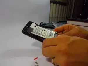
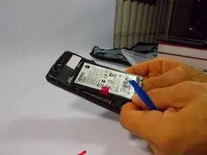
    • Use the plastic opening tool around the edges to loosen the battery.

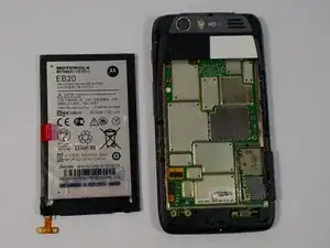
    • Once the battery is loose, carefully lift from the bottom edge and remove the battery.

  7. Wfke1lEgWCiiC3Ai
    • The battery may now be removed.

  8. DNXyKPfePT2BlQUn
    DNXyKPfePT2BlQUn
    XktoB5WNvYbEcuqQ
    B5BdQSgD1AgwOVHQ
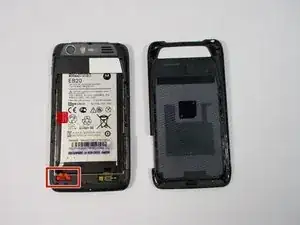
    • Begin by removing the back cover using the plastic opening tool. There are adhesive strips attached to the back cover, so take care when prying case to prevent cracking

    • The adhesive strips may stay on the back cover or the battery.

  9. pkBdQX6GK14sxun4
    pkBdQX6GK14sxun4
    FAXZNWJTTeRYmsme
    • The back case portion may be removed after the battery has been removed.

    • Use the T5 Torx screwdriver to remove the 10 coarse-thread 5mm screws

  10. cerfZsUtOJNYTsFg
    cerfZsUtOJNYTsFg
    aMMVHuUns4KHctnO
    WwrXFYlWQVU1RRWq
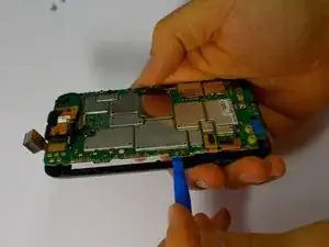
    • Now with the screws removed, use the plastic opening tool to lift the edges of the front assembly.

    • Continue to use the plastic opening tool around the edges of the device to remove the front assembly.

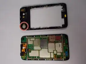
    • The speaker is located in the upper corner of the case. It it attached with adhesive and can be removed by gently prying with the plastic opening tool

  11. sMuUQ66DDvD6RZbP
    sMuUQ66DDvD6RZbP
    DA2q1ySnPQeRRPH5
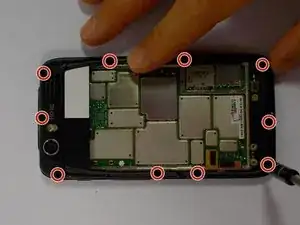
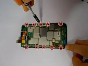
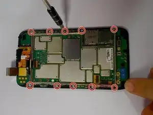
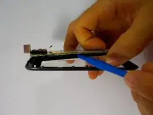
    • Begin by removing the 10 Torx T5 motherboard baseplate screws

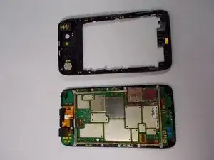
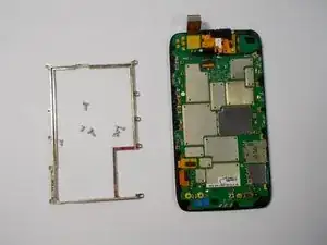
    • The back chassis can now be removed.

  12. 4JLuPTXfOUNODYYP
    4JLuPTXfOUNODYYP
    OJxsOKMSiWhbD1wB
    • Remove the 10 Torx T5 screws, that hold the metal frame to the motherboard.

  13. fRbQDbVEi3AYAEaW
    fRbQDbVEi3AYAEaW
    ZZBmgR2HMwrNh3Zq
    QypFteGxC4xvvnZs
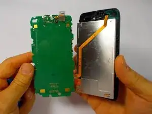
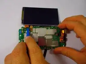
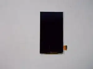
    • After following the steps to access the motherboard, you are ready to remove the touchscreen and LCD display.

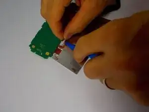
    • Use the plastic opening tool to separate the LCD display from the motherboard.

    • The touchscreen may separate from the LCD, however they are both connected to the motherboard as one unit.

  14. 2QE1MUIbJmvfUDIY
    2QE1MUIbJmvfUDIY
    TVloxsA1SBcZFSsL
    awkyOkvl2bdTohrh
    • Remove the ribbon cable from the back of the lcd using the plastic opening tool or spudger.

    • Use care removing the ribbon cables. They are very thin and are broken easily.

  15. bjiuamUvGYPTYpV4
    bjiuamUvGYPTYpV4
    tBJ3T2VKP3FK4RAW
    • Remove the ribbon cable connecting the LCD display to the motherboard, be mindful that the ribbon cable is very thin.

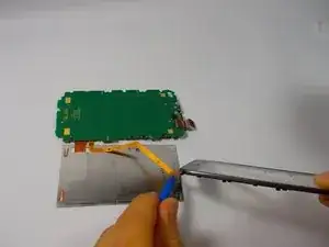
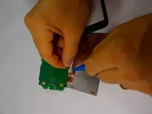
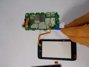
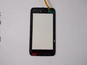
    • With the LCD display removed, remove the ribbon cable connecting the touchscreen to the motherboard

  16. rSLluQPU5VPMkh1v
    rSLluQPU5VPMkh1v
    tAK6cg55CjC2qZKR
    • The LCD display and the touchscreen may now be replaced.

  17. NfGrRRrr3JJPgCfK
    NfGrRRrr3JJPgCfK
    gMeEMY2suScF5FqF
    QMDe2fCvm51WShA4
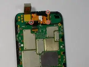
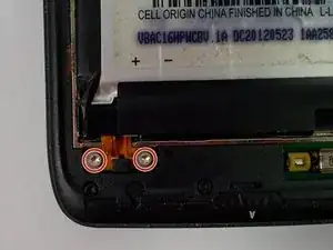
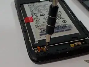
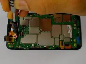
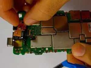
    • Remove the three Torx T5 screws that locks the front facing camera to the motherboard.

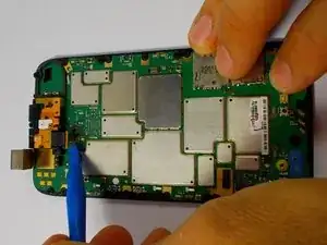
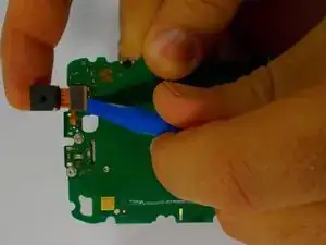
    • Use the plastic opening tool to lift the ribbon cable from the motherboard.

  18. 3KnETqAB3hCYlg6Q
    3KnETqAB3hCYlg6Q
    SS2SLMP6EFOURMHY
    XovteRlJQXiWDqYP
    • Lift the rear camera our of the motherboard.

  19. OWQL5aZ6NPXcsFXP
    OWQL5aZ6NPXcsFXP
    fKfEwPssxDM1eh4V
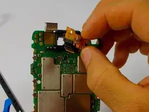
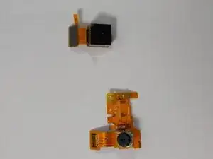
    • Use the plastic opening tool to lift the ribbon cable connector from the motherboard.

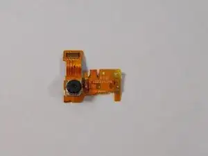
    • Now both front and rear cameras have been removed.

Conclusion

To reassemble your device, follow these instructions in reverse order.

Bradley Hinckley

Member since: 28/10/15

561 Reputation

0 comments