Introduction
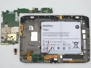
If your Motorola Xoom 2 is still having issues after attempting the troubleshooting and other repair guides, you may need to replace the device motherboard. This guide will demonstrate how to replace the motherboard of the Motorola Xoom 2.
Note: This should be last resort option, if the device is not fixed after replacing the motherboard, consider responsibly recycling the device.
-
-
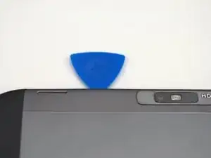
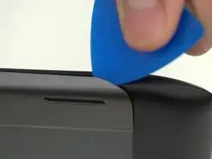
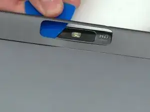
Pry off the silver top back cover (the panel around the camera) with iFixit opening picks or a similar implement.
-
-
-
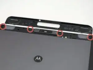
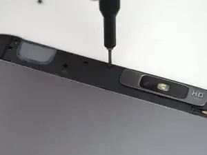
Using a T5 screwdriver, unscrew the four 1.5mm screws holding the main back cover. These screws are arranged in a line across the top of the back of the device.
-
-
-
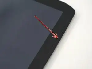
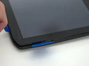
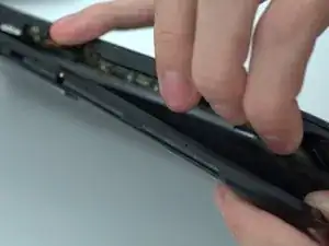
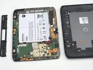
Turn the device over and using a pry tool and the opening picks, gently apply pressure between the outside edge of the seal marked with the arrow. Slowly move around the edges of the device, applying even pressure, and separate the back plate from the display.
-
-
-
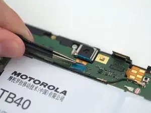
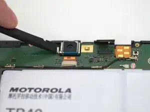
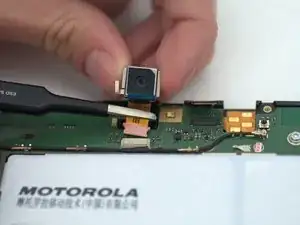
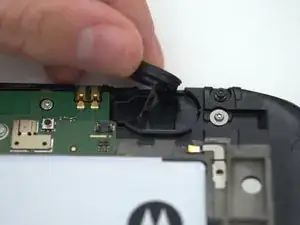
Using a spudger, carefully pry and remove camera assembly using the small pry point as shown.
-
After removing the camera from the housing, use tweezers and pull gently to remove the connector from its housing.
-
-
-
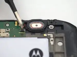
Using tweezers or a prying tool, gently disconnect the speaker connector cable from the motherboard.
-
-
-
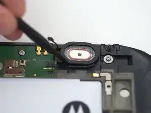
Using a prying tool or a spudger, gently apply pressure to the gap between the speaker and the plastic chassis and lift the speaker out of the device.
-
-
-
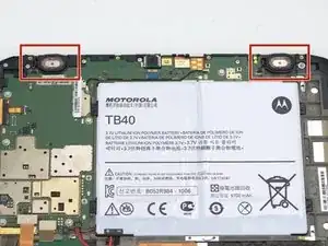
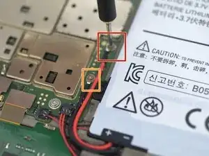
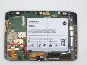
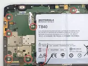
Disconnect the battery first for safety by unscrewing the two 1.5mm screws with a T5 Torx screwdriver.
-
-
-
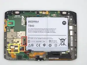
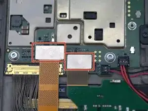
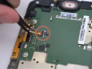
The following steps will take place within the outlined red sector.
-
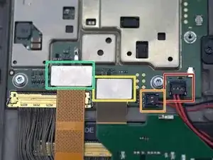
The connectors will be removed in this order: red, orange, yellow, then green.
-
-
-
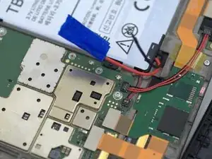
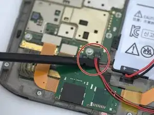
Begin by removing this three-wire connector with a spudger or similar pry tool as shown.
-
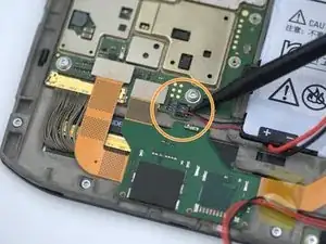
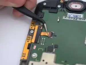
Next remove the smaller two-wire connector in the same way as the first.
-
-
-
Using a prying tool or a spudger, disconnect the following connectors by applying upward force from underneath the connections.
-
-
-
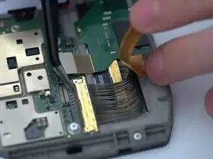
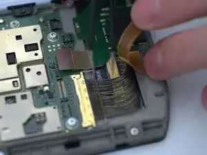
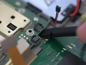
Using your fingers, gently pull back the connector. Using tweezers pull up the 'handle' of the connector located underneath. This handle is resting in front of the yellow-gold metal strip where the wires meet.
-
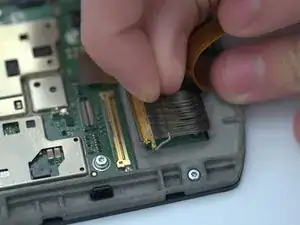
Once the handle has been pulled up and rotated back to a more accessible position, you will be able to grab it with your fingers. Pull the handle back to disconnect it from the device.
-
-
-
Remove the following six 1.5mm screws using a T5 Torx screwdriver.
-
Once all connectors and screws have been removed from the motherboard, it is ready to be pried up and removed.
-
-
-
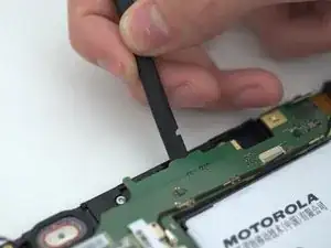
Begin prying up the motherboard in the corner nearest the battery. Not much force will be required as the board is completely loose at this point.
-
Next, pry the motherboard up at the top of the device near the left speaker.
-
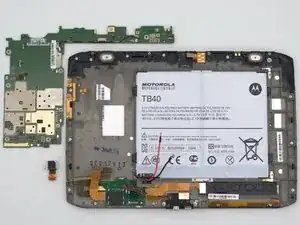
Once you can get the edge of the board high enough, grab it and lift it up and towards the battery. This will prevent it from snagging on the cable disconnected in step 7.
-
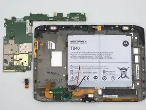
To reassemble your device, follow these instructions in reverse order. Leave the battery unplugged until the back plate need to be added on.