Introduction

Replacing the Power supply will require soldering

  1. vGeitExnSUgOYSQb
    vGeitExnSUgOYSQb
    nTPcp3CB64yLvHGF
    • Place the monitor face down on a clean, flat surface.

  2. DSDHlH2pqSOMyKlZ
    DSDHlH2pqSOMyKlZ
    1CQkuiutoIleACPU
    • Firmly remove the back panel of the stand by pulling it up and away from the monitor.

  3. veabGbw2ONiILEeg
    veabGbw2ONiILEeg
    pghNodDKVeUFCjFW
    • Unscrew the two 6mm Phillips PH2 screws to detach the stand enclosure from the stand.

  4. U1CQ1qS6MRRLJGje
    U1CQ1qS6MRRLJGje
    VMA4OZXPGHKp6iaC
    • Firmly grasp the stand enclosure with your hand and slide it to base of stand.

  5. CCxI5AXXpaDwUlBT
    • Unscrew the two 14.5mm Phillips PH2 screws holding the stand to the monitor.

  6. nTgn5hX2diWLVat2
    nTgn5hX2diWLVat2
    24k5hkAp56RbGLk1
    • Lift the the stand straight up to remove it.

  7. JVDomSlEUEMxqTLD
    JVDomSlEUEMxqTLD
    U1nrtrOfVFsPdDxB
    1KxRP1vUlq6bLOvI
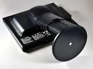
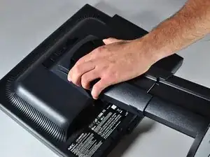
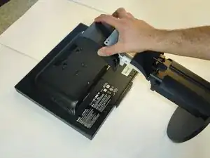
    • Place the monitor screen face up.

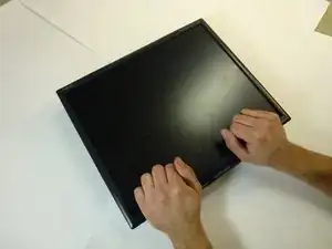
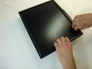
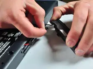
    • Pull the frame off by placing your fingers on the inside of the frame and pulling out and up, the frame should snap off.

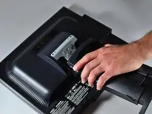
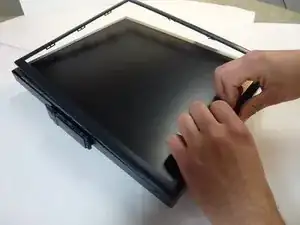
    • Continue your way around the screen.

  8. Rowxq5yg6mhuxLsK
    Rowxq5yg6mhuxLsK
    qODvSoIfmIESYJAv
    V1SBuTVPyynfmEdj
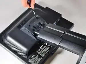
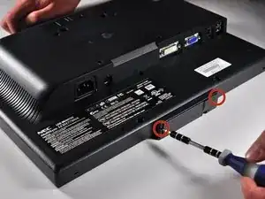
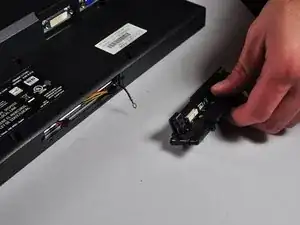
    • Unscrew the two 7mm screws from the bottom of the button assembly.

    • Do not pull the button assembly out too quickly or with too much force! Damage to the wires can occur.

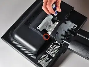
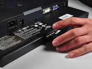
    • Pull the button assembly out a few inches and unplug the colored cables.

  9. m2YnEXD4SJSmoEKm
    m2YnEXD4SJSmoEKm
    M2wPRifMaerrBWVR
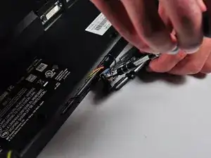
    • Unscrew the gold colored 7mm Phillips PH000 screw holding the button assembly to the monitor.

    • Remove the button assembly from the monitor.

  10. XSq2T22fxcpTtZBu
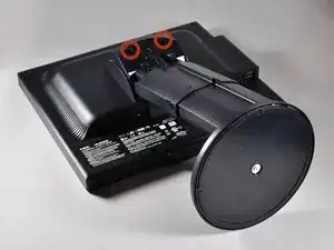
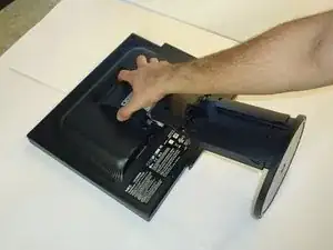
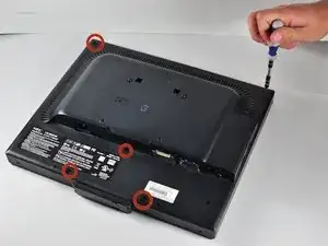
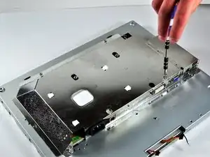
    • With the monitor face-down, unscrew the 5 7mm Phillips PH2 screws around the outside of the enclosure.

  11. Fi2jvD4XlcabofHm
    Fi2jvD4XlcabofHm
    45D1maFHqiVAjCan
    MBX1LbAAu5JP1Btr
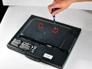
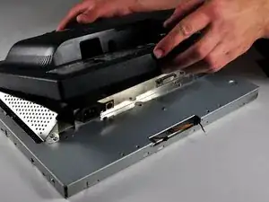
    • Unscrew the 2 14.5mm Phillips PH2 screws located on the raised center of the enclosure.

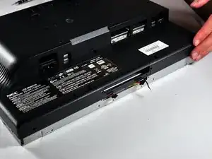
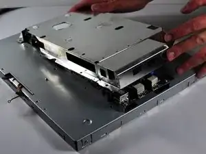
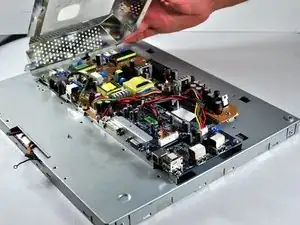
    • Carefully pull the enclosure off the monitor.

  12. 2tTLpZBoSUQETaYw
    2tTLpZBoSUQETaYw
    OTbpQYDyExqREYkO
    • Unscrew the 10 5mm Philips PH2 screws holding the metal casing to the monitor.

  13. 3iSKh2AjMDqtVyev
    3iSKh2AjMDqtVyev
    gnsoXHvLOVBeEugC
    • Pull the the metal casing off of the monitor to reveal the motherboards.

    I have a similar monitor and the power switch is broken. I need to get inside and try to fix it

    Thank you

    Richard Morgan -

  14. N54HDCgJseymo5hJ
    N54HDCgJseymo5hJ
    1HmG5ZGC6oKj6Sna
    MXCYsDLDYNfDGESi
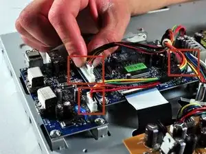
    • Make a note or use a pen to mark which plugs correspond to which colors. (Pink or Blue)

    • Remove the four plugs on the brown circuit board by pulling up on the tabs and wiggling them out. You could also use a spudger to help you lift little clips holding them in.

  15. LObbBTJ4XlX25EYW
    LObbBTJ4XlX25EYW
    hGNZ3sCyMcGJ1H55
    24b3VYtQ2q1CfSQE
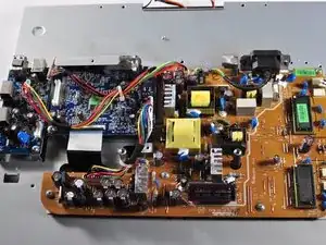
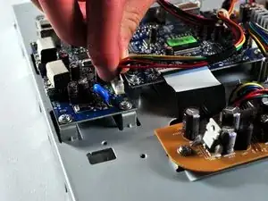
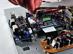
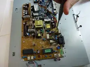
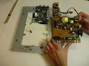
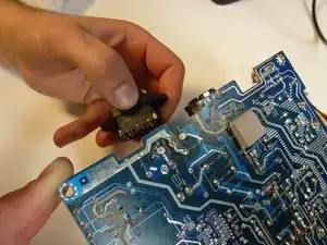
    • Locate the several multi-wire connectors on the board.

    • These connect several parts of each board together and consist of several different colors of wires. There is also a zip-tie holding the two sets of wires together that you can cut if it is getting in your way.

    • Disconnect the three plastic connectors from the blue colored boards by pulling them up while wiggling them.

    • Some force is necessary, it may also help to use the Large Needle Nose Pliers.

  16. xRx5ufSrIWnG6LJG
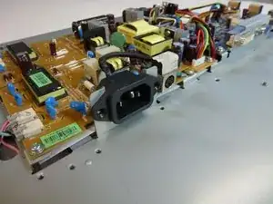
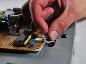
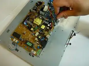
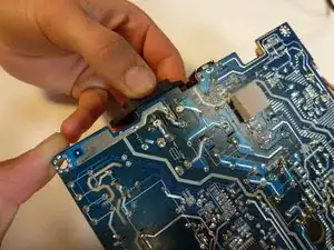
    • Locate the large black power plug.

    • Using a Phillips #1 Screwdriver, unscrew the two 8mm colts holding the black tabs to the metal frame.

  17. a2kcsBTcuZRALA5C
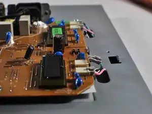
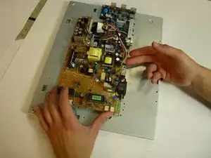
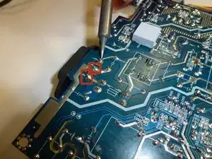
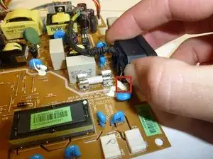
    • Locate and remove the gold colored 10mm Philips screw located near the black power plug. It holds in a wire that connects to the power plug.

  18. H1vJeRL1u1pAJSsQ
    H1vJeRL1u1pAJSsQ
    AG5IJIfi5wFVBDI5
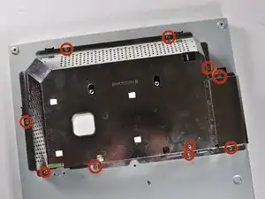
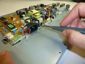
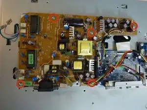
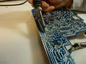
    • Remove 5 8mm Phillip1 screws, with a Philips 1 screwdriver, located in various places on the board.

  19. MF3xoRTgjHtZXYsq
    MF3xoRTgjHtZXYsq
    pdxLR2rGh4WGybjJ
    • Lift the brown power supply board off of the frame and set it aside.

  20. yxEOcnXllPfENhBD
    yxEOcnXllPfENhBD
    5FGnCkUMLMjAddp4
    • Remove the solder from the three joints attached to the power input.

  21. ltcj3mXsDdkAGZBX
    ltcj3mXsDdkAGZBX
    fdXCM2jR5ScDxpgI
    SQx2osRPCdmImAKr
    • Grab hold of the power supply jack and remove it from the power supply board.

    • A little force and a wiggling action may be needed to remove the power supply jack from the glue.

    Good job man

    Marcio -

Conclusion

To reassemble your device, follow these instructions in reverse order.

Charlie Mohr

Member since: 22/10/13

332 Reputation

0 comments