Introduction
If your Nikon Coolpix P4 does not turn on after charging it or replacing the battery, you may need to replace the motherboard. This guide will tell you how to replace your Nikon Coolpix P4 motherboard.
The motherboard is what operates communications between the different parts of the camera. It is also what controls the entire camera. A faulty or broken motherboard will prevent your camera from working.
Before beginning, make sure you have a new motherboard ready to replace the old one, turn off your camera, make sure it's not plugged into the charger, and remove the battery.
-
-
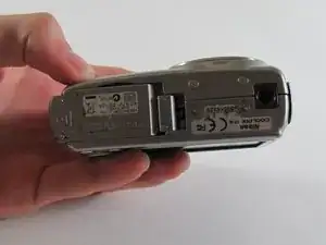
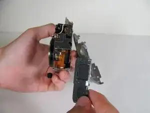
Open the battery door. Inside is the memory card and the battery.
-
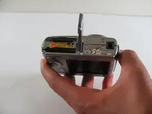
Click over the orange tab and take out the battery.
-
Close the battery lid by pushing it down and sliding it back.
-
-
-
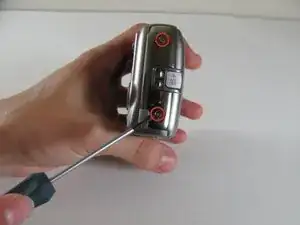
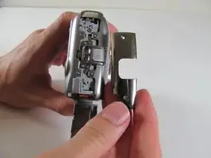
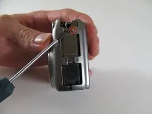
Remove panel on right side (front view) by removing these two screws. (.196in screws)
-
Remove single screw set underneath panel. (0.083in screw)
-
-
-
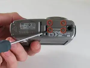
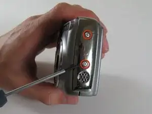
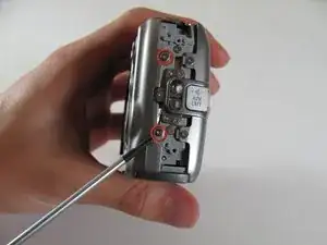
Remove three screws as shown. (Right screw:0.084in, Left screw:0.088in, Middle screw:0.114in)
-
-
-
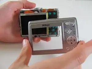
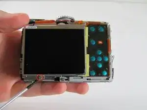
Carefully pull orange LCD connector up and out of the port.
-
Be careful to pull vertically while pushing the black tab upwards
-
-
-
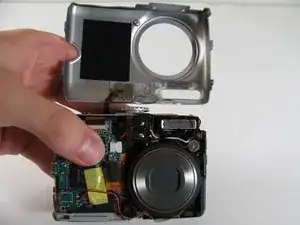
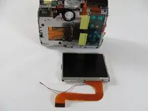
You can now remove the LCD from the camera body.
-
Insert new LCD and reassemble using the steps in reverse order.
-
-
-
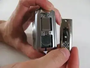
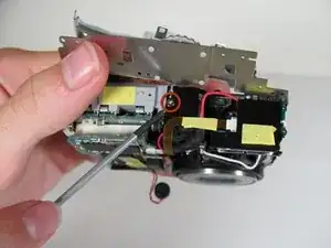
Use a Phillips #00 screwdriver to remove the two 2.9 mm screws on the right side of the camera.
-
-
-
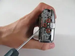
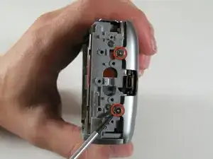
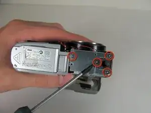
Use a Phillips #00 screwdriver to remove the seven 2.8 mm screws from the back of the camera.
-
-
-
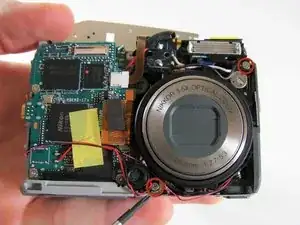
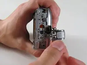
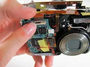
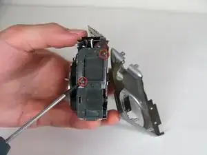
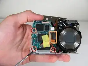
Detach the cable that connects the lens to the left side of the motherboard by firmly grasping the cable's base and pull it gently away from the socket.
-
-
-
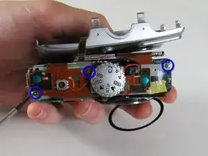
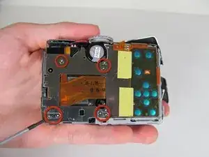
Use a Phillips #00 screwdriver to remove the three 2.8 mm screws from the motherboard.
-
Detach the orange tab with the foam on top.
-
-
-
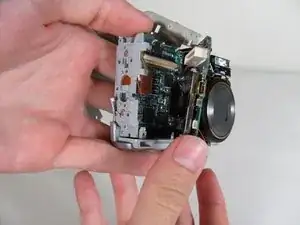
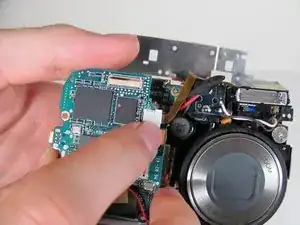
Carefully remove the tab that connects the flash to the motherboard from the port by gently pulling the connector to the right and out of its port.
-
-
-
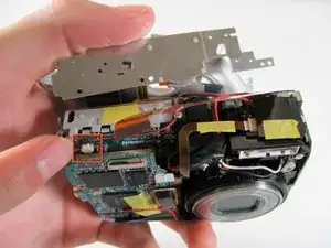
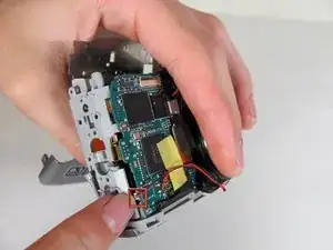
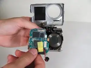
Remove the motherboard from the camera body.
-
Replace it with a new motherboard.
-
Follow the steps in reverse order to reassemble it.
-
To reassemble your device, follow these instructions in reverse order.