Introduction
-
-
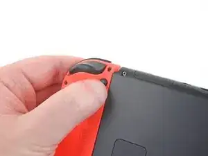
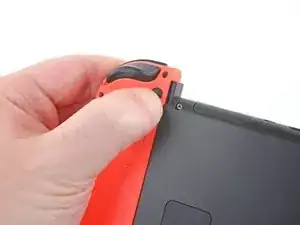
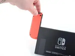
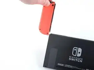
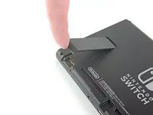
Press and hold down the small round button on the back of the Joy Con controller.
-
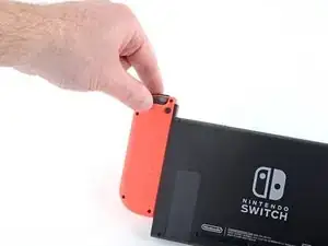
While you hold down the button, slide the controller upward.
-
-
-
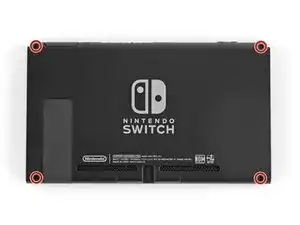
Use a JIS 000 driver or an official iFixit PH 000 driver to remove the following screws securing the rear panel:
-
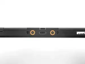
One 2.5 mm-long screw on the top edge of the device
-
Two 2.5 mm-long screws on the bottom edge of the device
-
-
-
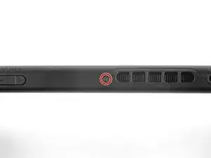
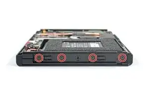
Use a JIS 000 screwdriver or an official iFixit PH 000 driver to remove the two 3.8 mm center screws on the sides of the device (one on each side).
-
-
-
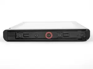
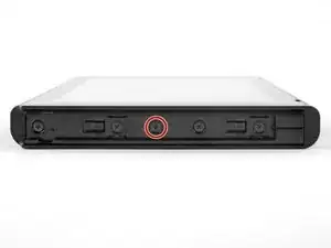
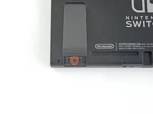
Use a JIS 000 screwdriver or an official iFixit PH 000 driver to remove the 1.6 mm screw in the kickstand well.
-
Close the kickstand.
-
-
-
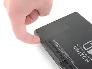
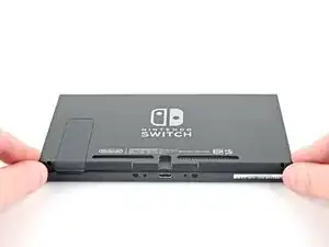
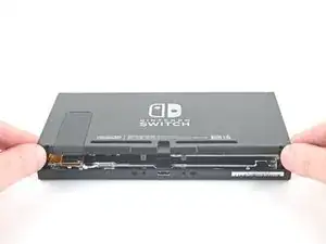
Open the game card cartridge flap.
-
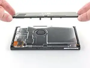
Lift the rear panel up from the bottom of the device and remove it.
-
-
-
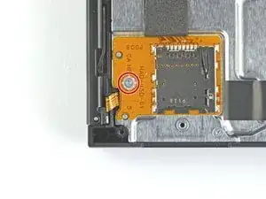
Use a JIS 000 screwdriver or an official iFixit PH 000 driver to remove the 3.1 mm screw securing the microSD card reader to the device.
-
-
-
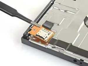
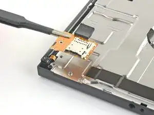
Use your fingers or a pair of tweezers to lift the microSD card reader straight up from the device to disconnect and remove it.
-
-
-
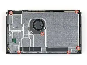
Use a JIS 000 screwdriver or an official iFixit PH 000 driver to remove the six 3 mm screws securing the shield plate to the device.
-
-
-
Use your fingers or a pair of tweezers to peel back the piece of foam on the top edge of the device near the fan exhaust port.
-
-
-
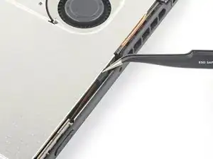
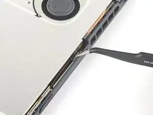
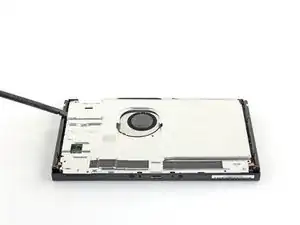
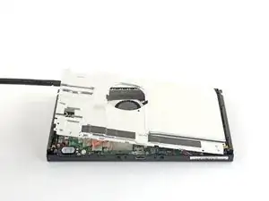
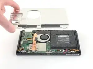
Insert a spudger underneath the shield plate along the edge of the device.
-
Pry up to lift the shield plate and remove it from the device.
-
You can reuse the pink thermal compound if you're careful. Keep the compound clean and make sure it makes solid contact between the heat sink and the shield during reassembly.
-
If you need to replace it, refer to our thermal paste guide to remove the old thermal compound and replace it with an appropriate compound, such as K5 Pro, during reassembly.
-
-
-
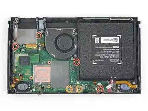
Use the point of a spudger to pry the battery connector straight up and out of its socket on the motherboard.
-
-
-
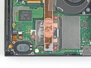
Use a JIS 000 screwdriver or an official iFixit PH 000 driver to remove the three 3 mm screws securing the heat sink to the motherboard.
-
-
-
Carefully peel the two foam pieces stuck over both the heatsink and the fan away from the fan.
-
Insert the point of a spudger underneath the part of the foam that isn't stuck against anything,
-
Press the top of the foam with your finger to hold it in place.
-
Roll the spudger tip underneath the foam all the way to the other end of the foam to release it.
-
-
-
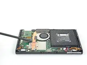
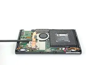
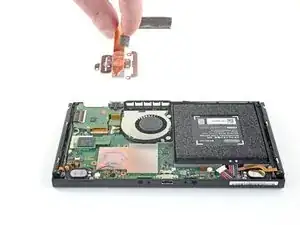
Use a spudger or your fingers to lift the heatsink up and off the motherboard to remove it.
-
Apply thermal paste to all surfaces that had thermal paste applied previously. This includes between the heatpipe and aluminum shield, which the Switch uses as additional heatsinking.
-
-
-
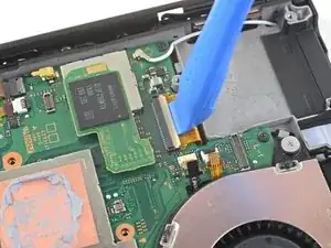
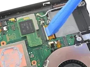
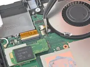
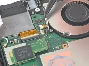
Use an opening tool or your fingernail to flip up the small, hinged locking flap on the digitizer cable's ZIF connector.
-
-
-
Use a pair of tweezers to slide the digitizer cable horizontally out of its connector on the game card reader board.
-
-
-
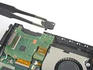
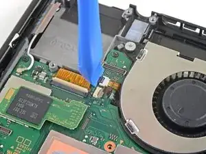
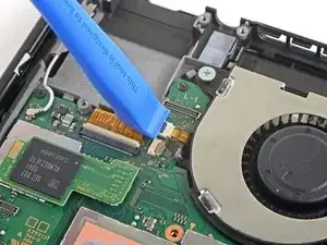
Use the point of a spudger to pry the headphone jack and game card reader connector straight up to disconnect it from the motherboard.
-
-
-
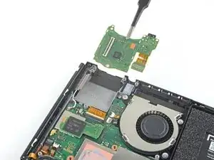
Use a JIS 000 screwdriver or an official iFixit PH 000 driver to remove the three 3.1 mm screws securing the headphone jack and game card reader board to the device.
-
-
-
Use a pair of tweezers or your fingers to remove the headphone jack and game card reader board.
-
-
-
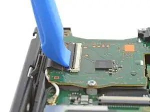
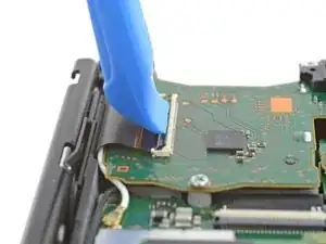
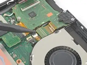
Use an opening tool, spudger, or your fingernail to flip up the small, hinged locking flap on the LCD ribbon cable ZIF connector.
-
-
-
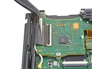
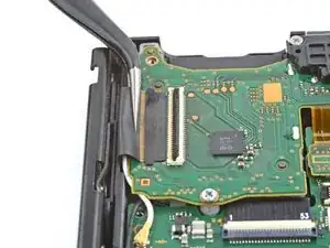
Use a pair of tweezers to pull the ribbon cable straight out of its connector on the motherboard.
-
-
-
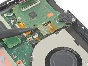
Use an opening tool, spudger, or your fingernail to flip up the small, hinged locking flap on the fan cable ZIF connector.
-
-
-
Use a pair of tweezers to pull the fan cable straight out of its connector on the motherboard.
-
-
-
Use an opening tool, spudger, or your fingernail to flip up the small, hinged locking flap on the power and volume button ribbon cable ZIF connector.
-
-
-
Use a pair of tweezers to pull the ribbon cable straight out of its connector on the motherboard.
-
-
-
Use an opening tool, spudger, or your fingernail to flip up the small, hinged locking flap on the smaller LCD ribbon cable ZIF connector.
-
-
-
Use a pair of tweezers to pull the ribbon cable straight out of its connector on the motherboard.
-
-
-
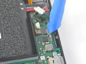
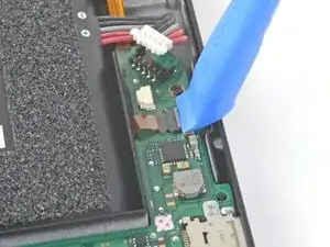
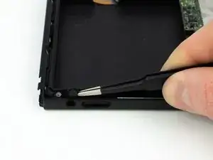
Use the point of a spudger, an opening tool, or your fingernail to flip up the small, hinged locking flap on the Joy Con sensor rail's data cable ZIF connector.
-
-
-
Use a pair of tweezers to pull the ribbon cable straight out of its connector on the motherboard.
-
-
-
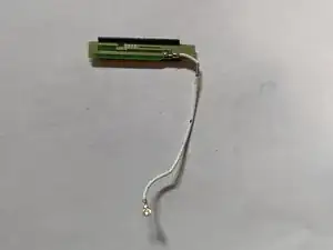
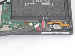
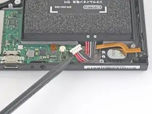
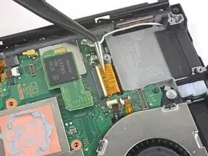
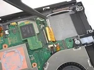
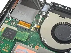
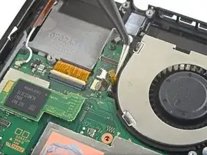
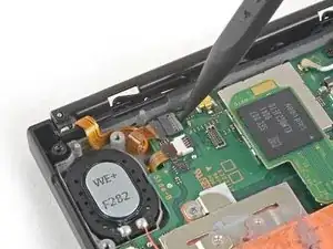
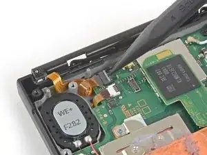
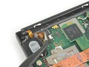
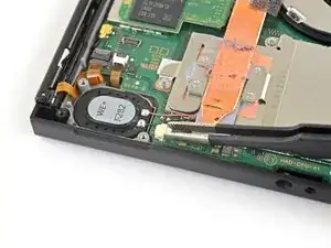
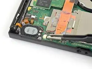
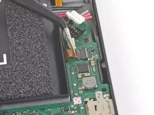
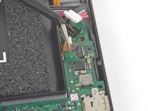
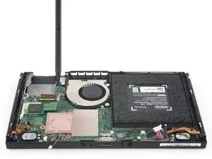
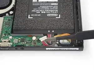
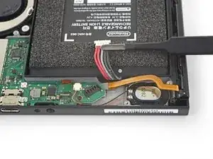
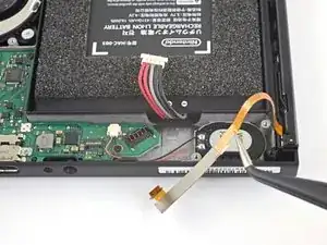
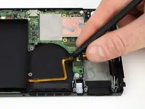
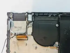
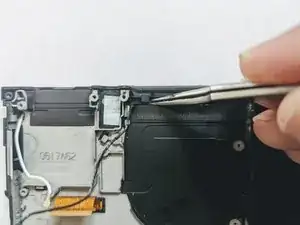
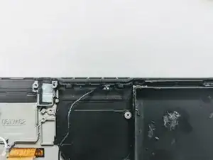
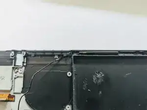
Use the point of a spudger to pry up the black antenna cable straight up out of its socket on the motherboard.
-
-
-
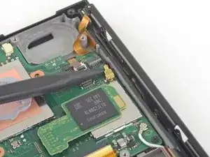
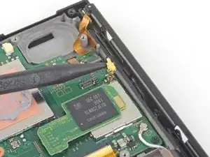
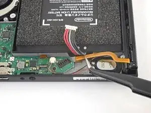
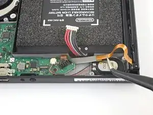
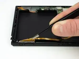
Use the point of a spudger to pry up the white antenna cable straight up out of its socket on the motherboard.
-
-
-
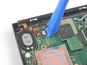
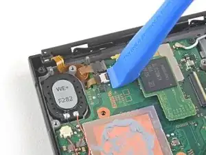
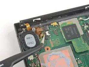
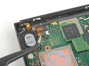
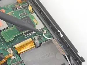
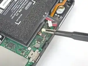
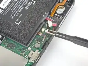
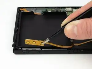
Use your fingers or a pair of tweezers to pull the right speaker connector straight out of its socket on the motherboard.
-
-
-
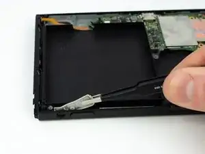
Use your fingers or a pair of tweezers to pull the left speaker connector straight out of its socket on the motherboard.
-
-
-
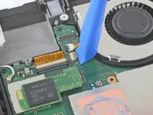
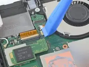
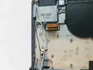
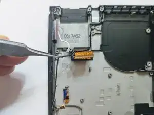
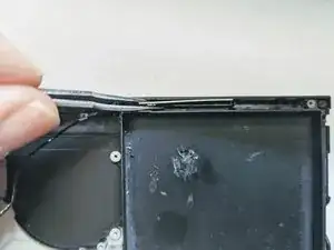
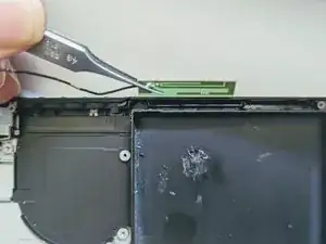
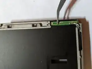
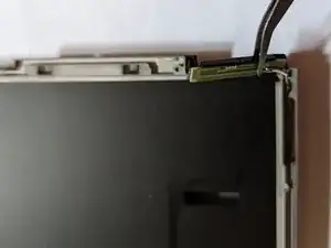
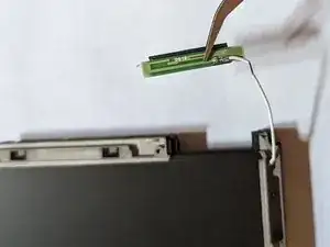
Use an opening tool, spudger, or your fingernail to flip up the small, hinged locking flap on the Joy Con sensor rail data cable ZIF connector.
-
-
-
Use a pair of tweezers to slide the Joy Con rail data cable straight out of its connector on the motherboard.
-
-
-
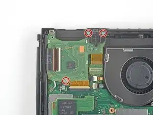
Use a JIS 000 screwdriver or an official iFixit PH 000 driver to remove the following screws:
-
Four 2.5 mm screws
-
Two 3.1 mm screws
-
-
-
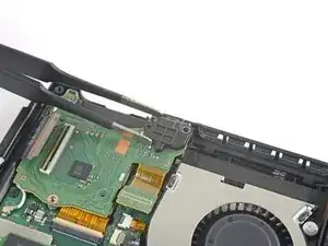
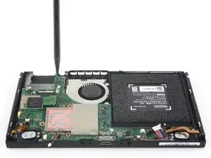
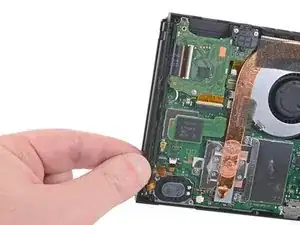
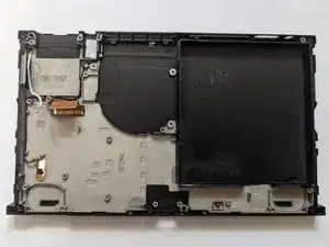
Insert a spudger into a gap between the motherboard and the frame.
-
Carefully lift up the motherboard and remove it from the frame.
-
-
-
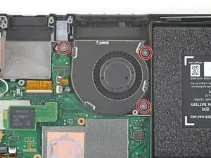
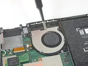
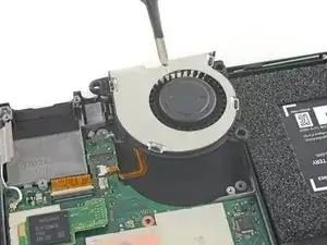
Use a JIS 000 screwdriver or an official iFixit PH 000 driver to remove the three 4.8 mm screws securing the fan.
-
-
-
Use a pair of tweezers or your fingers to lift the fan straight up and remove it from the device.
-
-
-
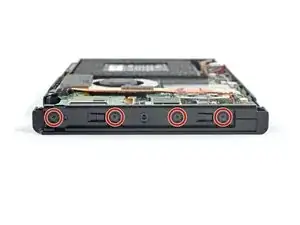
Use a JIS 000 screwdriver or an official iFixit PH 000 driver to remove the four 3.7 mm screws securing the right Joy Con rail to the frame of the device.
-
-
-
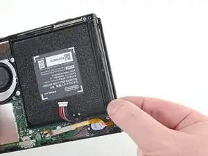
Use your fingers or a pair of tweezers to lift the battery connector up and out of the way of the Joy Con rail's data cable.
-
-
-
Use your fingers or a pair of tweezers to lift the battery connector up and out of the way of the Joy Con rail's data cable.
-
-
-
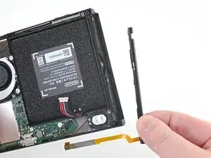
Use a JIS 000 screwdriver or an official iFixit PH 000 driver to remove the four 3.7 mm screws securing the left Joy Con rail to the frame of the device.
-
-
-
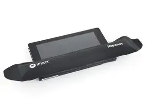
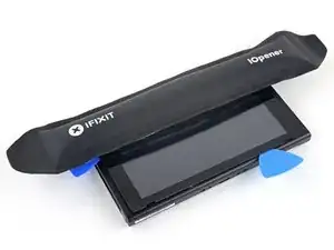
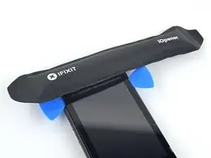
Heat an iOpener and apply it to the bottom edge of the screen for around two minutes to to help soften the adhesive.
-
-
-
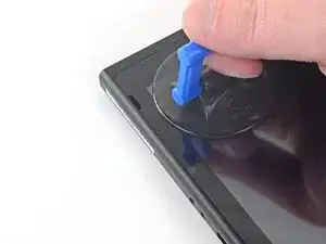
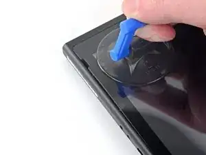
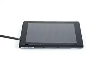
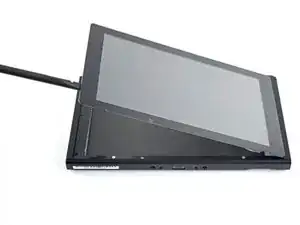
Apply a suction cup to the bottom-left corner of the screen.
-
Pull up on the suction up with strong, steady force to create a gap.
-
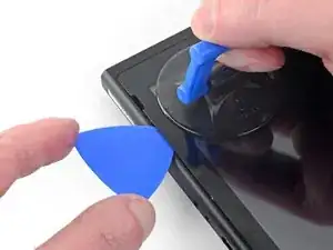
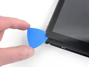
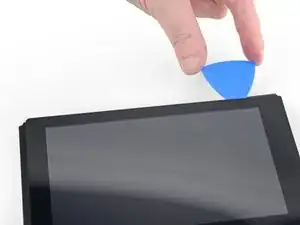
Insert the point of an opening pick into the gap, making sure to only insert the pick about 5 mm.
-
-
-
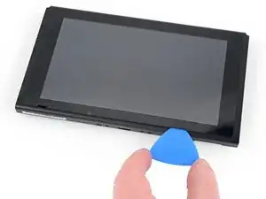
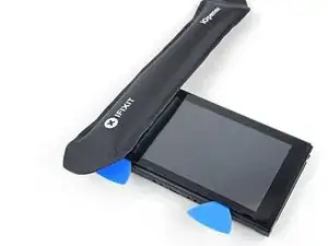
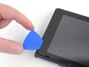
Slide the opening pick along the bottom edge of the screen to slice the adhesive.
-
Leave the pick inserted to prevent the adhesive from re-adhering to the frame.
-
-
-
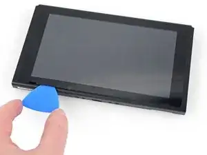
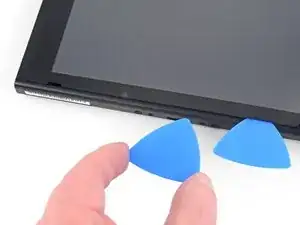
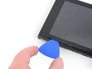
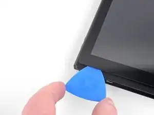
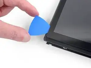
Insert a second opening pick into the gap to the left of the first pick.
-
Slide the opening pick back towards the left side of the device.
-
Leave the opening pick inserted.
-
-
-
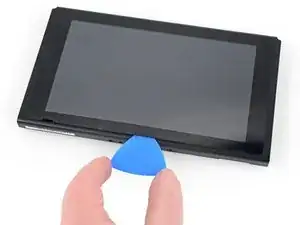
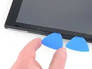
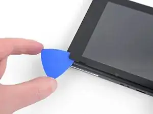
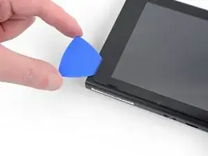
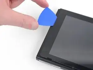
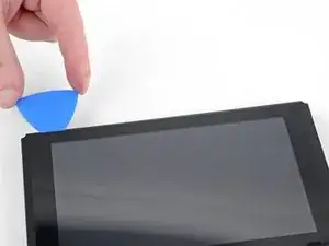
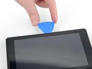
Continue sliding the opening pick around the top-left corner of the screen to slice the adhesive.
-
-
-
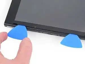
Heat the right edge of the screen for around two minutes to help soften the adhesive.
-
Place the flat end of a spudger into the gap along the left edge of the screen.
-
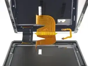
Carefully and slowly lift the left edge of the screen, opening it like a book.
-
-
-
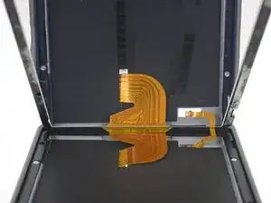
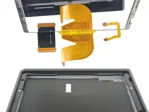
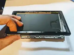
Lift the right edge of the screen straight off the device, threading the ribbon cables through the frame as you do so.
-
-
-
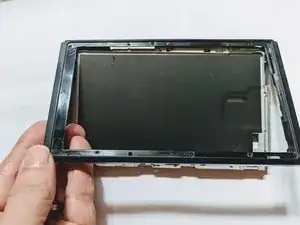
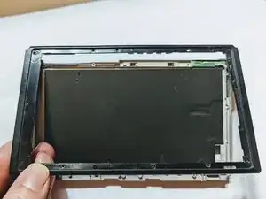
Lift the front edge of the frame then slide the frame up toward the top of the display to remove it.
-


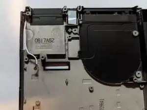
To reassemble your device, follow these instructions in reverse order.

Kann ich diese Anleitung auch für die OLED anwenden? Habe im INet sonst leider nichts brauchbares gefunden.
Ina Barz -