Introduction
Use this guide to replace a broken screen on your Nokia G42 5G.
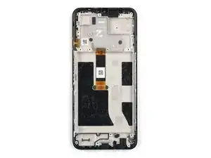
This guide is written for the genuine Nokia G42 5G screen assembly. The assembly consists of the screen and midframe together as one part. Make sure you have the correct part before you begin this repair.
Note: This procedure requires transferring your phone's internals into the new assembly.
For your safety, turn on your phone and allow the battery to discharge below 25% before starting this procedure. This reduces the risk of fire if the battery is accidentally damaged during the repair. If your battery looks puffy or swollen, take extra precautions.
-
-
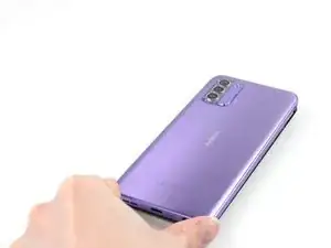
Power down your phone and unplug any cables.
-
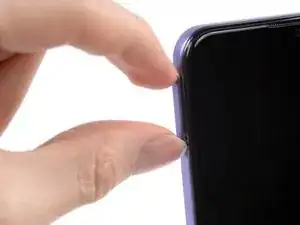
Insert a SIM eject tool, bit, or a straightened paper clip into the small hole on the SIM card tray on the upper left edge of the phone.
-
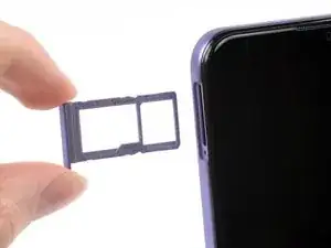
Press firmly to eject the tray.
-
-
-
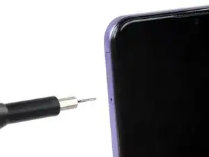
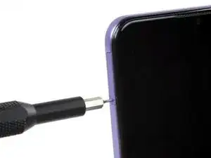
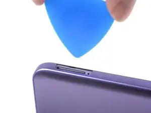
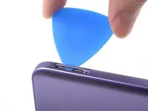
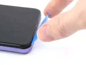
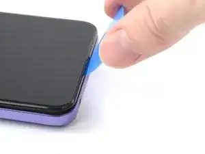
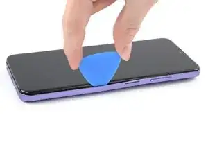
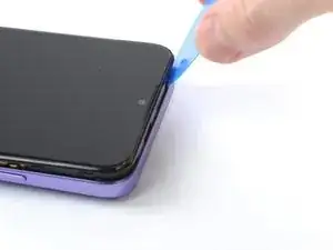
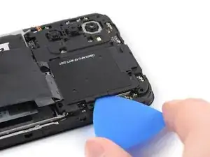
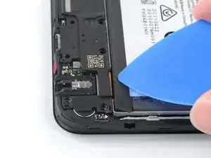
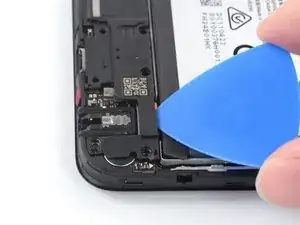
Position the opening pick at a steep downward angle between the back cover and the screen assembly.
-
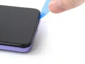
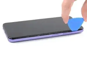
Slide the opening pick down the left edge of the phone to release the plastic clips.
-
-
-
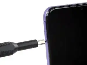
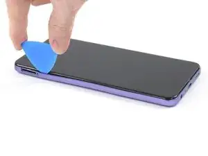
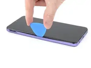
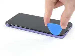
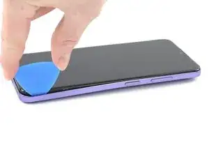
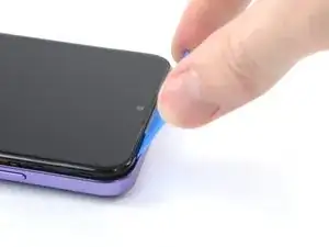
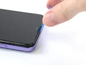
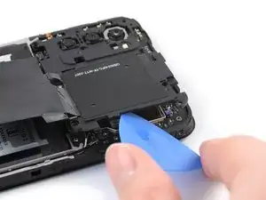
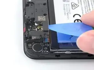
Turn the opening pick around the corner and continue to slide it along the bottom edge to release the plastic clips.
-
-
-
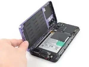
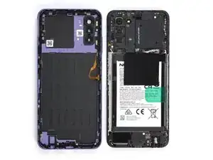
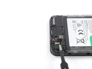
With the phone laying screen-side down, carefully lift the right edge of the back cover, opening it like a book.
-
Lay the back cover next to the phone.
-
-
-
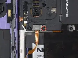
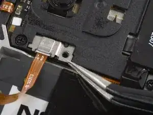
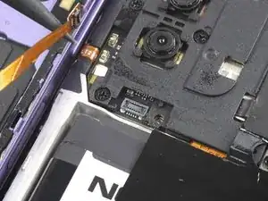
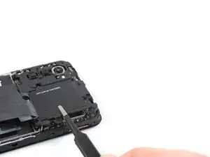
Use a Phillips screwdriver to remove the 3.8 mm‑long screw securing the fingerprint reader bracket.
-
-
-
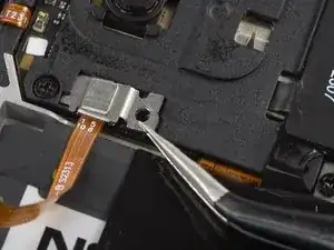
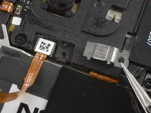
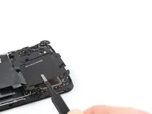
Use the pointed end of a spudger to disconnect the fingerprint reader by prying the connector straight up from its socket.
-
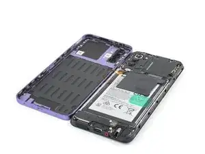
Remove the back cover.
-
-
-
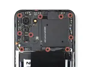
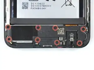
Use a Phillips screwdriver to remove the ten 3.8 mm-long screws securing the motherboard cover.
-
-
-
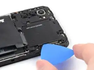
Insert an opening pick under the right edge of the motherboard cover.
-
Twist the opening pick to release the plastic clips.
-
-
-
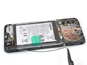
Use the flat end of a spudger to disconnect the battery cable by prying the connector straight up from its socket.
-
-
-
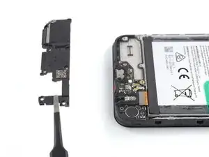
Insert an opening pick underneath the top right edge of the loudspeaker.
-
Twist the opening pick to release loudspeaker from the plastic clips holding it in place.
-
-
-
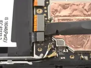
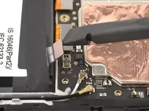
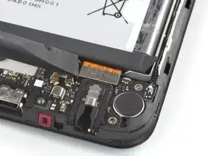
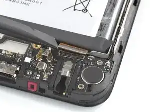
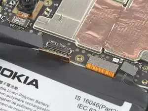
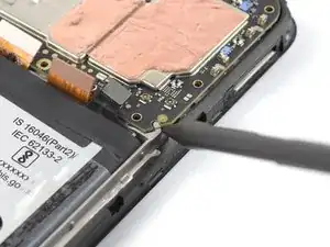
Use the flat end of a spudger to disconnect the interconnect cable by prying the connector straight up from its socket.
-
-
-
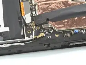
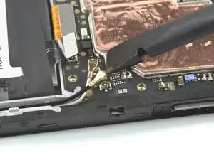
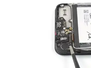
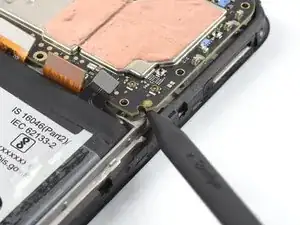
Use a spudger to disconnect both antenna cables by prying their connectors straight up from the sockets on the motherboard.
-
-
-
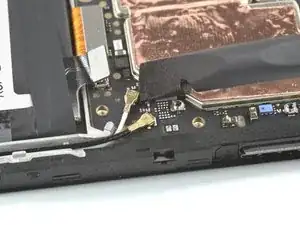
Use a pair of tweezers or your fingers to lift the antenna cables out of their recess in the frame.
-
-
-
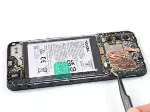
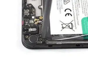
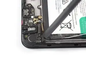
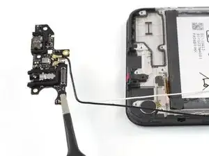
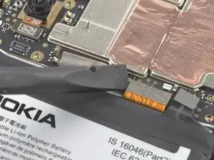
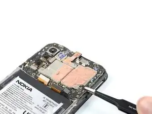
Insert the flat end of a spudger underneath the top right edge of the charging port assembly.
-
Pivot the charging port assembly up until you can grip it with your fingers.
-
-
-
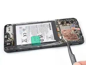
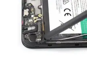
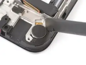
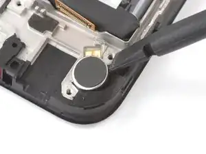
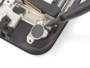
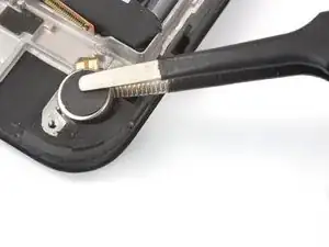
Insert the flat end of a spudger into the small recess on the upper right side of the vibration motor.
-
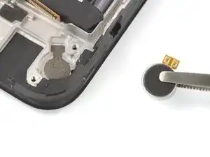
Pivot the spudger up to pry up the vibration motor off of the adhesive securing it underneath.
-
-
-
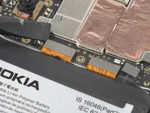
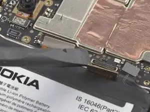
Use the flat end of a spudger to disconnect the display cable by prying the connector straight up from its socket.
-
-
-
Use the flat end of a spudger to disconnect the interconnect cable by prying the connector straight up from its socket.
-
-
-
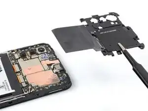
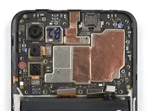
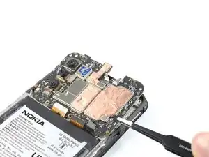
Insert the pointed end of a spudger underneath the bottom right corner of the motherboard.
-
Pry the motherboard up until you can grip it with your fingers.
-
-
-
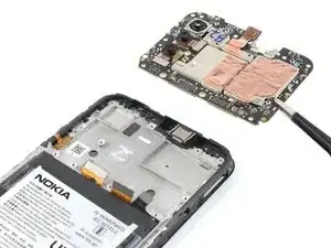
Grip the motherboard on the right edge using a pair of tweezers or your fingers.
-
Remove the motherboard.
-
-
-
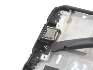
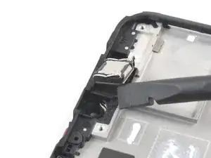
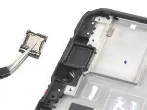
Insert the flat end of a spudger underneath the bottom left corner of the earpiece speaker and pry it out of its recess.
-
Remove the earpiece speaker.
-
-
-
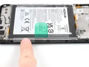
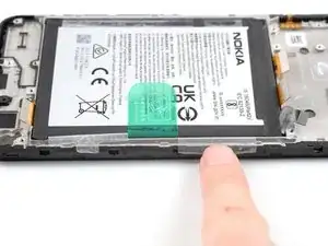
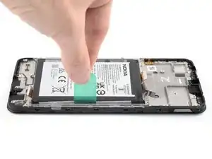
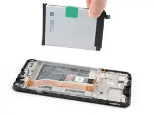
Use your fingers to peel the center green pull tab off of the battery.
-
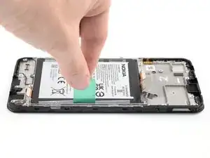
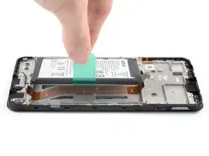
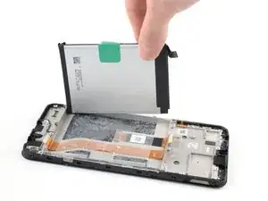
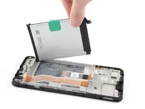
Using one hand to hold the phone steady, use your other hand to slowly and steadily lift the center green pull tab up to separate the adhesive securing the battery underneath.
-
If you have any difficulties with stubborn battery adhesive, you can contact Nokia's phones support.
-
-
-
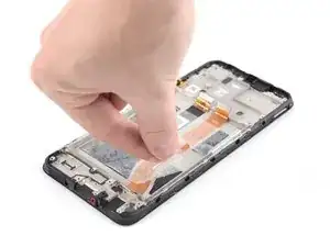
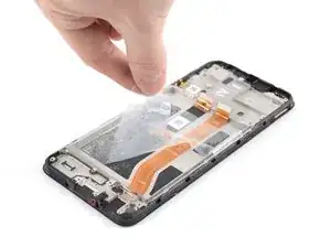
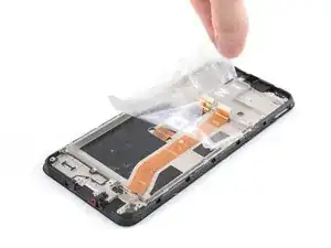
Grab the bottom right edge of the leftover adhesive film.
-
Pull the film towards the top of the phone with steady force to remove it.
-
Reattach the adhesive film to the battery.
-
Align the bottom edge of the battery (the edge without adhesive) with the bottom edge of the recess.
-
Lower the battery down and press firmly to secure it in place.
-
-
-
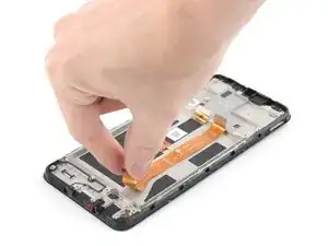
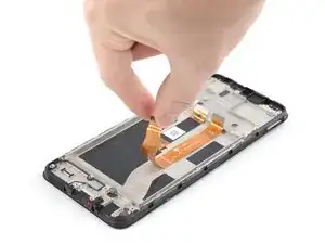
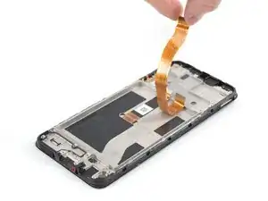
Grab the bottom of the interconnect cable and peel it up towards the top of the phone to remove it.
-


To reassemble your device, follow these instructions in reverse order.
Take your e-waste to an R2 or e-Stewards certified recycler.
Repair didn’t go as planned? Try some basic troubleshooting, or ask our Answers community for help.