Introduction
If you noticed your volume buttons are not controlling your volume, and you have tried other methods of raising and lowering your volume, this guide will show you how to replace the volume buttons.
-
-
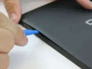
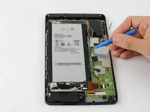
Starting at the Micro SD Card Slot and using the blue plastic opening tool, begin to maneuver the tool around the edges while applying light pressure to lift the panel upwards.
-
-
-
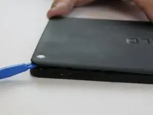
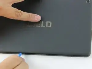
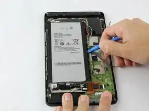
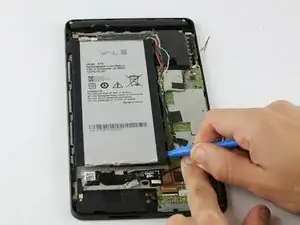
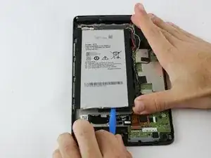
Continue lifting up the panel all the way around the edges of the tablet.
-
Once all of the panel clips are unfastened, gently remove the back panel.
-
-
-
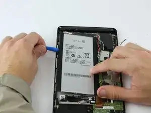
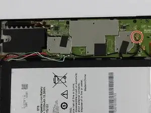
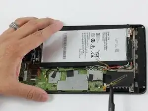
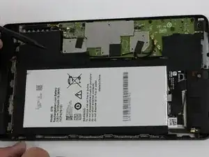
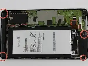
Using the blue plastic opening tool, place the lip of the tool underneath the battery as seen in the photo.
-
-
-
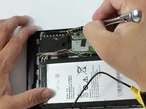
Once you have the blue plastic opening tool underneath the battery, work the tool around the edges of the battery similar to the technique used for the back panel.
-
-
-
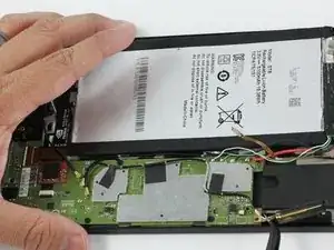
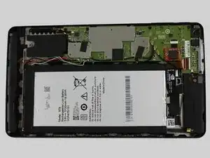
When the battery seems loose enough, use the blue plastic opening tool to lift the battery from the device.
-
-
-
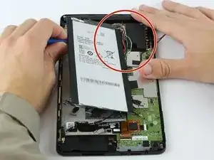
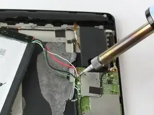
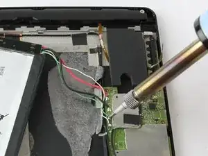
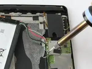
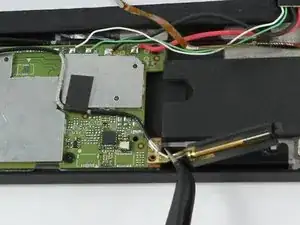
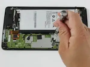
Using a soldering iron, desolder the four wires from the motherboard.
-
Once the wires are free from the motherboard, your battery should be free to remove from your device.
-
-
-
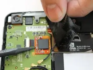
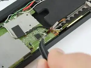
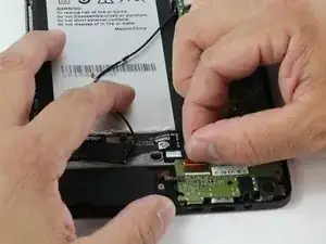
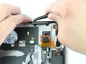
Use the angled tweezers to disconnect the black power cable from the mother board. The Cable should pop up from its slot when pulled.
-
-
-
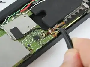
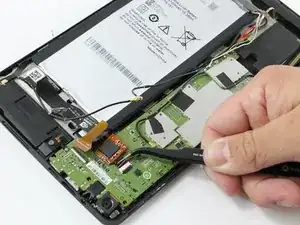
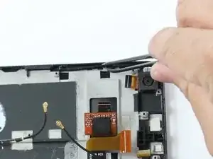
The black plastic piece of the antenna is attached to a copper colored film which can be pulled up using the tweezers.
-
The antenna should now be free from the device.
-
-
-
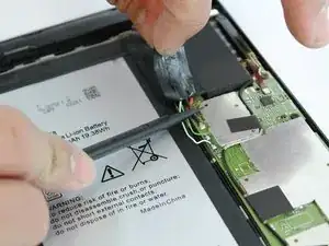
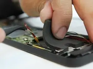
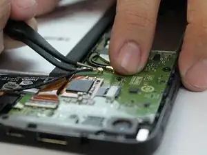
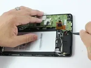
While using the black plastic spudger tool, slowly lift the tape with your fingers and hold the wires down with the tool.
-
-
-
Carefully remove the audio input films for each speaker from their respective ZIF (zero insertion force) connectors. These are the paper thin ribbons that have orange stripes along them.
-
Pull up the white latch on the ZIF connector, which will release the film and allow you to pull it out with tweezers.
-
Repeat this for both speakers.
-
-
-
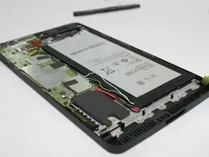
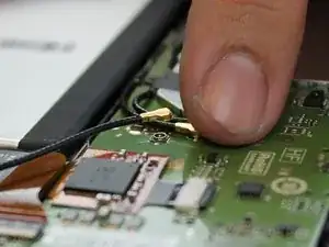
Remove the power cables connecting the speakers to the battery. These are black wires with gold tips.
-
Again, use the tweezers to carefully pull them up from their places, they should pop right off.
-
-
-
Free the speakers by removing their screws. You'll need the J000 Phillips-head screw Driver.
-
-
-
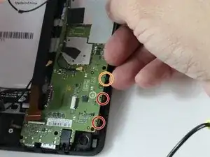
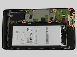
Remove the remaining screws holding the motherboard in place.
-
Screws description: 5 short black screw 20mm length and 30mm diameter.
-
Screws description: 3 long black screw 40 mm length and 20 mm diameter.
-
-
-
Using your fingers, grasp the brown ZIF (Zero Insertion Force) tab and pull outward to disconnect.
-
There is an orange chip that is connected to a white ZIF (Zero Insertion Force). Remove this by using either your fingers or the tweezers.
-
-
-
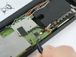
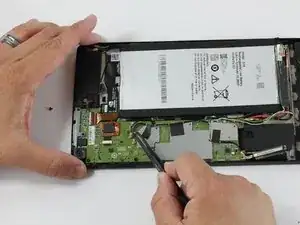
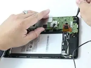
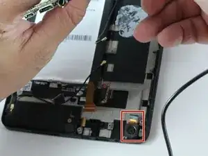
Using your tweezers, lightly lift around the edges to lift the motherboard.
-
Before lifting the motherboard out, use your tweezers to disconnect rear camera's copper cable from the motherboard.
-
-
-
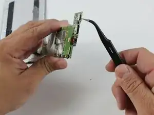
Use a soldering iron to desolder the Micro USB Port from the motherboard.
-
Now the Micro USB Port is free from the motherboard.
-
-
-
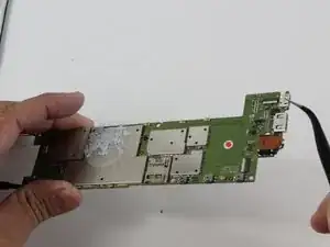
Here are the button switches that are pushed for your Volume Control.
-
This is your power button switch.
-
To reassemble your device, follow these instructions in reverse order.