Introduction
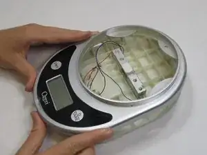
This guide explains how to remove the wires from the weight sensor each of the motherboards inside the Ozeri Pronto ZK14-S in separate steps. Assistance may be necessary if you do not feel confident about using the iOpener.
Tools
-
-
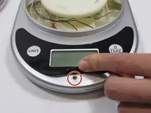
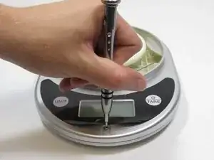
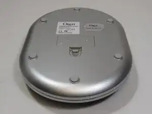
Pry off the sticker at the bottom where the “Ozeri” logo is to reveal a screw. The sticker does not need to be completely removed for the next step.
-
-
-
Using the 2.0 Flathead screwdriver, remove the 9.50 mm Phillips head screw under the sticker.
-
-
-
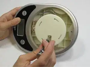
Using the 2.0 Flathead screwdriver, remove the two 18.76 mm Phillips head screws in the plate stand.
-
-
-
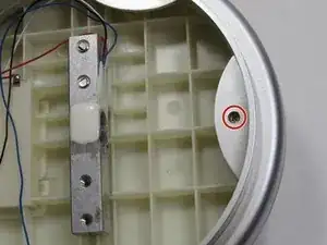
Using the 2.0 Flathead screwdriver, remove the 9.44 mm Phillips head screw on the end opposite of the LCD screen.
-
-
-
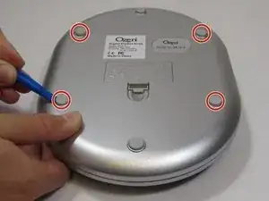
Using the plastic opening tool, pry off each of the two rubber stubs on the right side and the two stubs on the left side of bottom of the device.
-
-
-
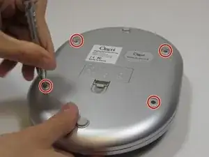
Using the 2.0 Flathead screwdriver, remove of the four 9.46 mm Phillips head screws under the removed stubs.
-
-
-
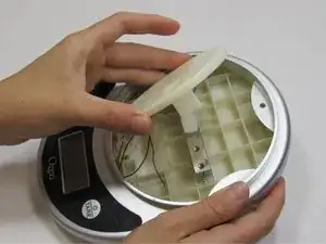
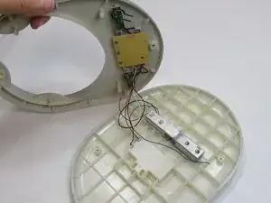
Pry apart the two panels to separate them from each other.
-
Flip the device over so the LCD is facing up. Flip the front panel over on its side.
-
-
-
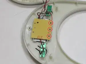
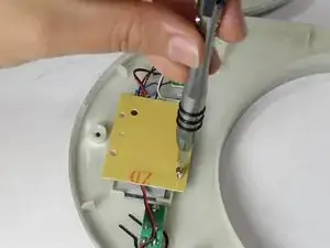
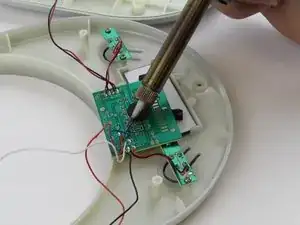
Using the 2.0 Flathead screwdriver, remove the three 7.20 mm screws on the back of the center LCD motherboard.
-
-
-
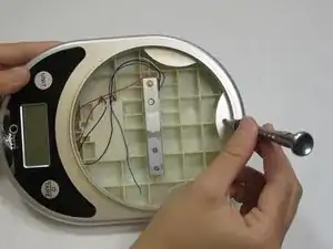
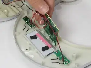
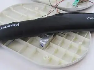
Using the iOpener, warm the glue on the weight sensor the other end of the damaged wire is attached to.
-
-
-
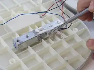
Using the nylon or metal spudger, detach the end of the damaged wire from the weight sensor.
-
To reassemble your device, follow these instructions in reverse order.