Introduction
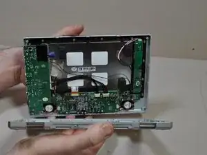
Replacement of the LCD power board is a relatively simple process. Many of the Polaroid 0700P's internal parts can be removed and replaced independently of each other.
-
-
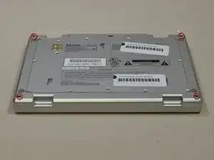
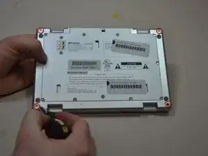
Turn the entire device over, so that the underside of the device is facing upward.
-
With the underside of the device facing up, locate the 11mm screw found in each far corner of the device. Remove the single 11mm screw from each of the four corners, using the Phillips #0 screwdriver.
-
-
-
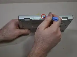
Turn the device so that the underside faces you, and the edge where the case and device bind, faces upward. The opening of the device should be face down.
-
In this position you will see a crease line between the device and the top cover. Gently Insert your blue plastic opening tool into the crack of the crease line, between the front and back cover to separate them.
-
Separate the halves of the case.
-
-
-
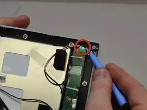
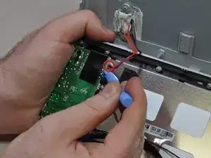
Locate the input/output board on the top left hand corner of the device. It will look like a green circuit board with wires protruding and connecting to the case cover.
-
Using your blue plastic opening tool, disconnect the multicolored wires located on the input/output board. These will be the same multicolored wires that connect the back cover to the input/output board.
-
-
-
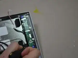
Find the LCD power board located on the top right hand corner of the device (The LCD power board will be the long green circuit board with a pink and white wire emerging from the top).
-
Using your blue plastic opening tool, remove the wire connections from the LCD power board located on the top of the board (These will be the pink and white wires).
-
-
-
Locate the two 5mm screws on the LCD power board. One screw will be in the top left corner, the second will be in the bottom right corner.
-
Remove the two 5mm screws with your Phillips #0 screwdriver.
-
-
-
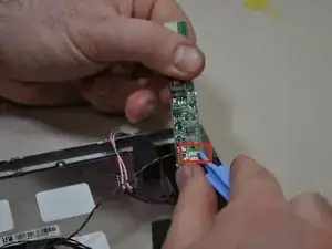
Lift the LCD power board out of the device (There will still be wires connecting the board to the device).
-
Vertically flip the LCD power board so that the side that was originally facing the device is now facing up. Using your blue opening tool, remove the connection (multi-colored and twisted wire) from the Input/Output board.
-

To reassemble your device, follow these instructions in reverse order.