Introduction
If you are having issues with the RAM memory and you need to replace it, it’s good to know that for this laptop there is enough room to upgrade it, and even to double it!
A standard HP ENVY 15 j100el indeed contains a RAM set composed by two Samsung memories of 4 GB each (Product code: M471B5173DB0-YK0; HP P/N (Part Number): 691740-001) but its memory slots manage to utterly handle as much as 8 GB per slot and therefore we can install an 8 GB memory module on each of the two slots in order to obtain a total RAM memory of 16 GB in this computer.
(The processor and the chipset of this notebook can even manage to handle a 32 GB RAM memory, but fortunately / unfortunately the single memory slot provided here can not cope with a single memory module of 16 GB)
Anyhow, the new memory modules should have the same characteristics of the original ones:
- Type . . . . . . . . . . . . . . . . DDR3L SDRAM
- Form factor . . . . . . . . . SO-DIMM (204 pin)
- CAS Latency . . . . . . . . CL 11
- Speed . . . . . . . . . . . . . . . 1600 MHz (PC3-12800)
- Voltage . . . . . . . . . . . . . 1.35 V
- Unbuffered & Non-ECC
-
-
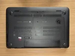
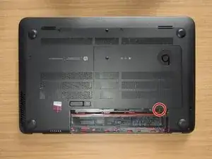
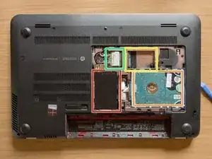
Turn the laptop upside down and gently lay it down on a flat surface.
-
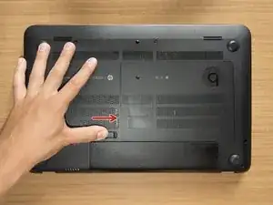
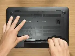
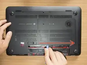
Slide the battery release latch to the right and the battery will pop up slightly.
-
While keeping the latch slid with one hand, grab the battery with the other hand and remove it by pivoting it upward.
-
-
-
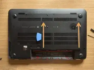
With an opening tool pry off the tabs that secure the service door to the base enclosure. Start with the long edge.
-
Continue along the short edges.
-
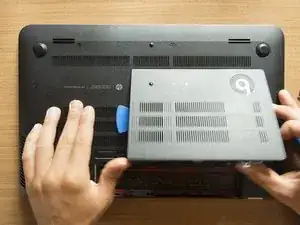
Once you have pried the service door off as it is in pic#3, it will come out of the rear edge very easily.
-
-
-
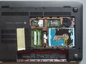
Without bending it, gently turn the RAM modules' protective flap to the left and stick it to the base enclosure with a piece of adhesive tape.
-
-
-
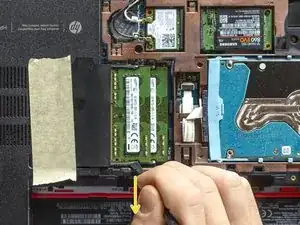
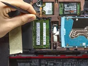
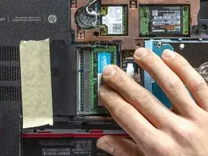
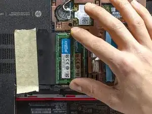
Take the spudger and place it over the bottom retaining arm so that the former can have a good grip on the latter. When you feel the grip, straightly towards yourself and quite forcefully, push the retaining arm off. You are going to hear a tiny click when the arm will be detached.
-
Repeat the last operation on the top retaining arm. This time pushing it off towards the opposite direction: as soon as you released the second arm also, the memory module will tilt up immediately.
-
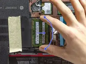
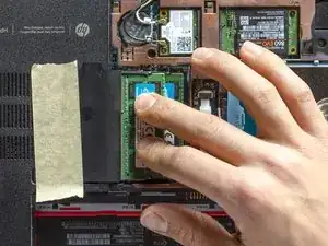
The top memory module is now released, and, if you're grounded, you can take it out of its slot. Grab the module as it is shown in pic#3 and - maintaining its inclination and making it lightly and repeatedly swing as a pendulum (btw left and right, as the bent blue arrow tries to show) - pull it out and put it away.
-
-
-
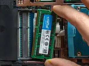
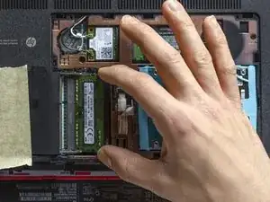
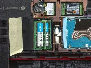
Are you grounded? If yes, take one of the new memory modules and align it with the connector by the correct side: the close-to-the-middle indentation of the module has to face the highlighted pin.
-
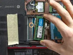
Then, keeping it tilted and carrying on the "pendulum" movement, gently push the module inside the slot. STOP when you feel you can't go any further: the new memory module should be now tilted and totally inside the connector - as it is shown in pic#2 - and the indentation of the module should almost be attached to the centring pin.
-
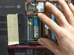
Once that the module is so positioned, gently press it down pushing it in the middle with your fingers until you hear a loud click: that sound means that the retaining arms have correctly grabbed the module and that the latter one has been successfully inserted!
-
You have successfully replaced the RAM memory! Congratulations :) Now remove the tape and reassemble the service door and the battery. Enjoy the new piece of hardware, cheers!