Introduction

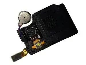
Remove the speaker/rear camera assembly from the Samsung Galaxy Attain 4G. This assembly includes the vibrator, rear-facing camera, flash, and loudspeaker.

  1. cpAsEfddlhE6ST5X
    • Begin by turn the device over to it's back, with the screen facing down.

  2. wVRmDESDia3VEdGK
    wVRmDESDia3VEdGK
    fYaRGeIwOOMus6a2
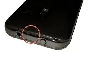
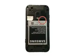
    • At the top of the device there is a small notch that is used to remove the battery door.

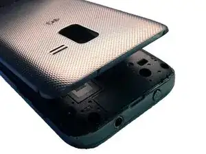
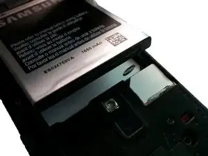
    • Using a pry tool or your fingernail, pry off the battery door from the main housing.

  3. diskIOcmMWLIqRwd
    diskIOcmMWLIqRwd
    fgKXxriMVTkkCQsy
    fjxUBXKUDyZDXLWD
    • Place the battery door to the side.

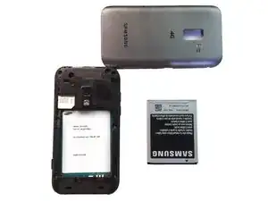
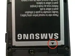
    • Using a pry tool or your fingernail, pry the battery up towards you.

    • You have now removed the battery!

  4. DLEOWeXZ3arAtFWj
    • Make sure when replacing the battery that the arrow on the bottom is facing down.

  5. H5C1XCoiYe4gy31Z
    • Remove the 6 Phillips head screws that hold the rear housing in place.

  6. IZQyENDUWmBtSorY
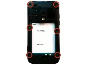
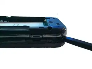
    • Using a spudger or plastic pry tool, slowly go around the phone between the display & rear housing to release the clips.

  7. tMoEO6qneacVDO1q
    • Lift the rear housing from the display assembly.

  8. rKKeWJwnYg4ktHBZ
    rKKeWJwnYg4ktHBZ
    csUcBtibdFpBP6Hk
    • Using your spudger/plastic pry tool, disconnect the headphone jack flex cable.

  9. 3VDFWhfKeRRWFyOK
    3VDFWhfKeRRWFyOK
    ZaXwEBkrSLUOJrCX
    • Using your spudger/plastic pry tool, disconnect the rear speaker flex cable.

  10. 4BqcuvEInBYbPYcS
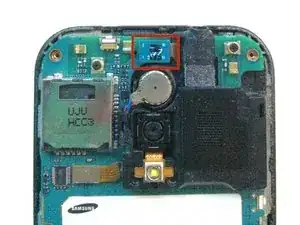
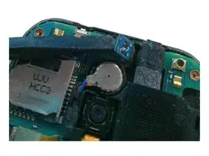
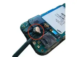
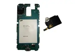
    • Using a spudger/pry tool, carefully remove the vibration motor from its housing. This has a mild adhesive on the bottom.

  11. gtuMcWSdUf1hRYUV
    gtuMcWSdUf1hRYUV
    Cb4JKTMytJEFhoBq
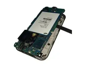
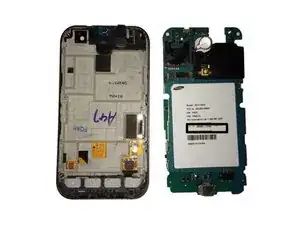
    • After removing both flex cables, slowly move the logic board to the left of the screen assembly.

    • Do not try and remove the logic board all the way, as you still have to remove the display assembly flex cable!

  12. DbiPexOJtuZdlNaa
    • Using your spudger/plastic pry tool, disconnect the LCD/Digitizer flex cable.

  13. XjsQjrN4YR1MDlif
    XjsQjrN4YR1MDlif
    GuiGvlWHRlOwNdUO
    • You have now removed the logic board from the display assembly.

  14. OVu4ZPI2vQDV41TZ
    OVu4ZPI2vQDV41TZ
    lSJ32xOY5qRB1ooN
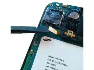
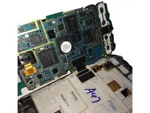
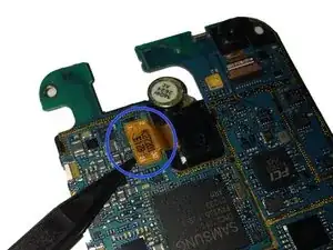
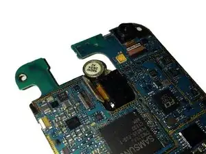
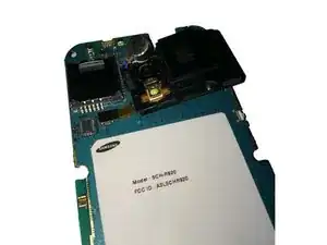
    • Flip the logic board to the rear side, and using a spudger/plastic pry tool to disconnect the rear camera flex cable.

  15. yUDlShITLYiGhHYK
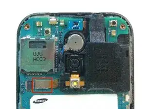
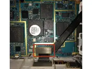
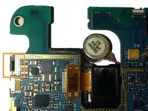
    • Flip the logic board to the front, and using a spudger/plastic pry tool to push the tension clip away from the board that holds the speaker/rear camera.

  16. wChP4CuVxNdJddpM
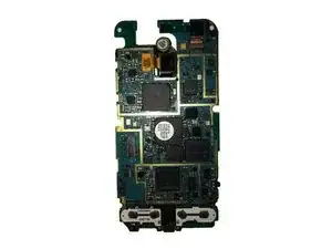
    • Flipping the board back over, remove the speaker/rear camera by lifting from the right side as shown.

    • Be careful not to rip the ribbon cable when you disconnect the speaker/rear camera cable connector.

  17. oV2o3qWJBYpSrqyg
    • The speaker/rear camera has now been removed from the board.

Conclusion

To reassemble your device, follow these instructions in reverse order.

Josh Forester

Member since: 28/11/10

2482 Reputation

0 comments