Introduction
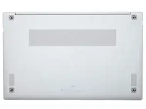
Use this guide to replace the motherboard in your Galaxy Book Pro 15" Laptop.
Before you begin, refer to the Samsung PC Repair Guide for safety information.
For your safety, discharge the battery below 25% before disassembling your device. This reduces the risk of a thermal event if the battery is accidentally damaged during the repair. If your battery is swollen, take appropriate precautions.
Note: Some photos show the heat sink removed. This is optional, as you don't need to remove the heat sink to remove the motherboard.
-
-
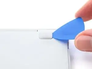
Insert an opening pick between the rubber foot and the rear case.
-
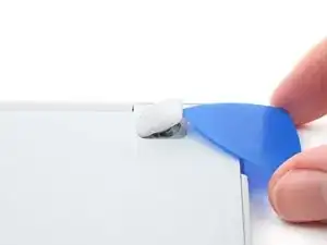
Pry up with the opening pick to release the clips securing the foot.
-
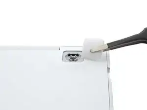
Remove the foot.
-
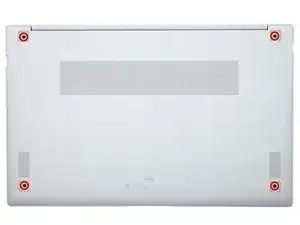
Repeat this procedure for the three remaining feet.
-
-
-
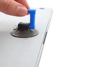
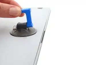
Apply a suction cup to the rear case, as close to the center of the bottom edge as possible.
-
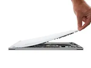
Pull up on the suction cup with strong, steady force to create a gap between the rear case and the frame.
-
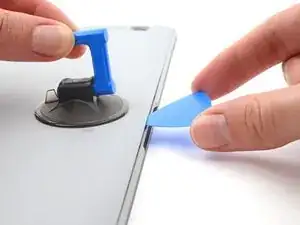
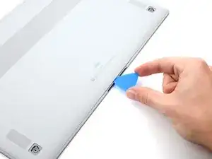
Insert an opening pick into the gap.
-
-
-
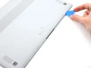
Slide the pick along the bottom edge of the rear case to release its plastic clips.
-
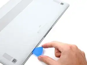
Repeat this process for the left and right edges, but stop before reaching the top edge.
-
-
-
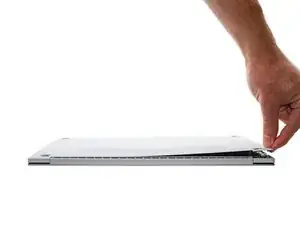
Pull the top of the rear case away from the frame to separate the adhesive and release the remaining clips.
-
Remove the rear case.
-
If you're using a using a genuine Samsung replacement rear case, be sure to peel off any adhesive liners from the rear case before securing the top edge's clips.
-
If you're reusing your rear case, you can use some pre-cut adhesive to re-adhere the top edge if your existing adhesive is no longer sticky.
-
-
-
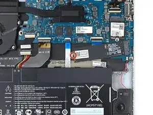
Insert a spudger between the frame and the bottom of the battery cable connector.
-
Pry up and disconnect the battery cable connector.
-
-
-
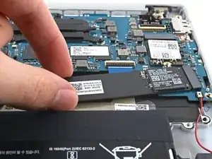
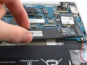
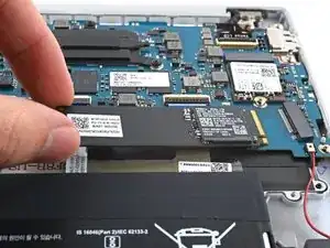
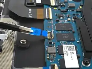
Lift the free end of the SSD up slightly and pull the SSD straight out of its socket on the motherboard.
-
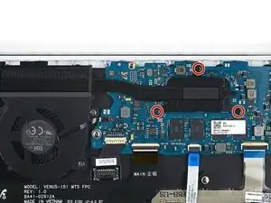
-
-
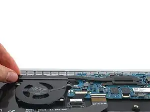
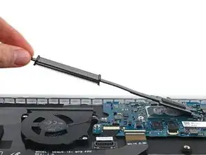
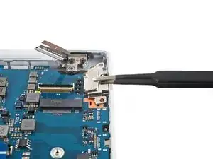
Lift the left edge of the heat sink upward to separate the heat sink from the motherboard.
-
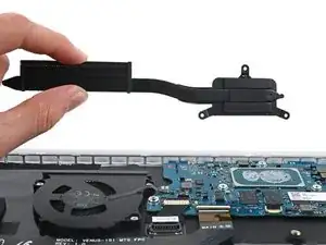
Remove the heat sink.
-
-
-
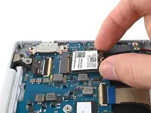
Lift the free end of the SSD up slightly and pull the SSD straight out of its socket on the motherboard.
-
-
-
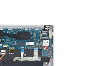
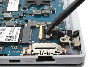
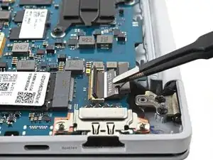
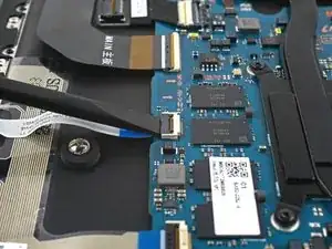
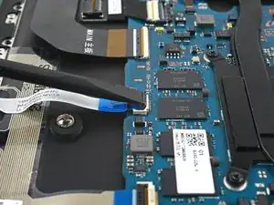
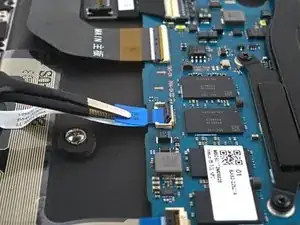
Use a spudger to pry up and disconnect the bottom right speaker connector from the motherboard.
-
-
-
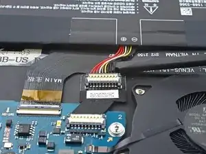
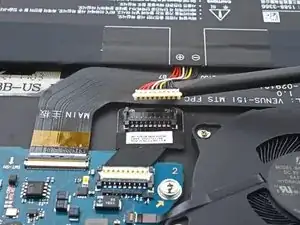
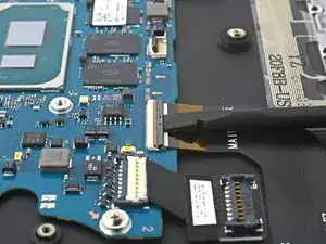
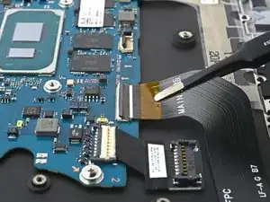
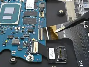
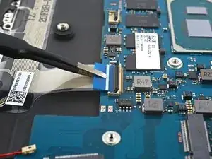
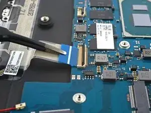
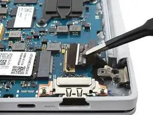
Use a spudger to gently pry up the locking flap on the motherboard ZIF connector for the interconnect cable.
-
-
-
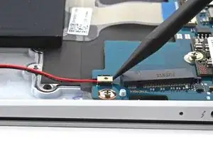
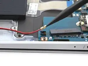
Insert a spudger between the frame and the bottom of the battery extender's cable connector.
-
Pry up and disconnect the battery extender's cable connector.
-
-
-
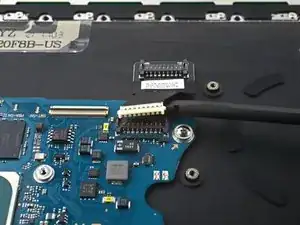
Use a spudger to gently pry up the locking flap on the ZIF connector for the keyboard cable.
-
-
-
Use a spudger to gently pry up the locking flap on the ZIF connector for the touchpad cable.
-
-
-
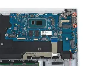
Use a Phillips screwdriver to remove the two 3.5 mm-long screws securing the motherboard port bracket.
-
-
-
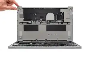
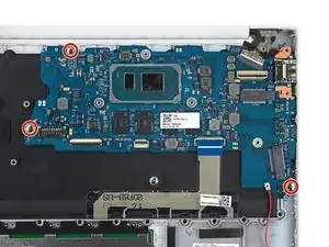
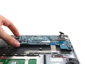
Lift the left side of the motherboard upward to separate it from its pegs on the frame.
-
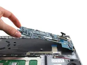
Lift the motherboard straight up to separate the rest of the pegs.
-
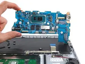
Remove the motherboard.
-


To reassemble your device, follow the instructions in reverse order and perform the opposite actions, e.g., "reattach" instead of "removing." Skip steps that use heating and prying, and pay close attention to the 📌 bullets as you work through the steps.
Take your e-waste to an R2 or e-Stewards certified recycler.
Repair didn’t go as planned? Check out our Answers community for troubleshooting help.