Introduction

Use this guide to replace or remove the iris scanner in your Samsung Galaxy S8 Active.

This guide involves removing the back cover of the device, so you will need replacement adhesive to reattach the back cover to the phone.

Before disassembling your device, be sure the battery is charged below 25%. If accidentally punctured or damaged, the battery can catch fire and/or explode; if discharged below 25%, the chances of fire/explosion is decreased.

  1. hJVBnbSELa2Jv2ku
    hJVBnbSELa2Jv2ku
    lUftGpNyusfPQIKR
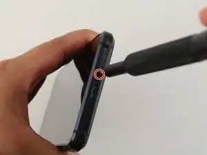
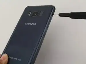
    • Insert and gently push the SIM card ejector tool (or an unfolded paperclip) into the small hole on the left side of the top edge of the phone.

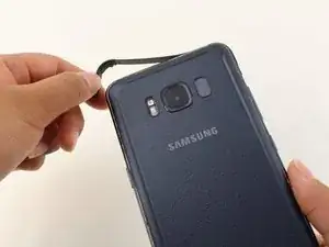
    • Press gently to eject the SIM tray.

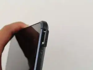
    • Remove the SIM card tray from the device.

    • To reinsert the SIM card tray, orient the SIM card with the gold contacts facing up and the notch to the bottom right. Reinsert the SIM card by pressing the card gently into the SIM tray slot.

  2. CI4hBaa6BB2X1TXw
    CI4hBaa6BB2X1TXw
    r6grOpMaIXZ4eMHp
    KIOIjgJnvJBvnYlK
    • Removing the back cover of the S8 Active will compromise its waterproof seals. Have replacement adhesive on hand before you proceed, or be sure to avoid exposure to liquid if you do not replace the adhesive when you reassemble the device.

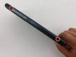
    • Remove four black 3mm screws from the outside edges of the device that hold the rubber bumpers in place using the TR6 Torx Security Screwdriver.

    • Take off the rubber bumpers from the top and bottom edges of the device.

    not needed as near as I can tell

    jason davis -

  3. 4KGCxRMHF23RkWVP
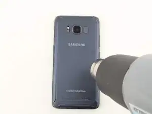
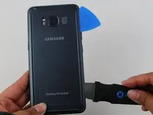
    • Use a heat gun to lightly heat the edges of the back to soften the adhesive that connects the back cover to the rest of the frame.

    • An iFixit iOpener, hair dryer, or hot plate can also be used to heat the edges.

    • Using a heat gun, hair dryer, or hot plate will make the metal frame rather hot to the touch, so handle it with care.

    • Be careful not to overheat the device –the OLED display, battery and other internal parts can be damaged by excessive heat. Approximately one minute should be enough to soften the adhesive.

  4. oSmMteTFlqJfrI4D
    oSmMteTFlqJfrI4D
    PMI1jiSHeEQMTGCN
    aEJdrClhRtc4PWKB
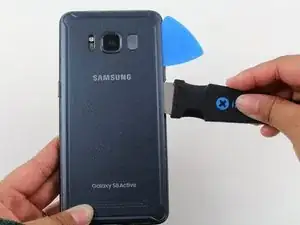
    • Insert the Jimmy tool under the edge of the back cover.

    • Because of the texture of the back cover, a suction handle does not provide any grip to help lift the back cover.

    • Once the Jimmy tool is under the edge of the cover, insert an opening pick into the seam to prevent the seam from closing if the Jimmy tool slips or is accidentally removed.

    • Cut slowly around the top section of the device and be careful to avoid damaging the cables for the fingerprint sensor and camera. Avoid prying too far into the top of the device to protect the fingerprint sensor.

    • Slide the Jimmy tool down the sides of the device, separating the adhesive.

  5. sfxm3VWbyLT4TlHk
    • Use the opening pick to slice through any remaining adhesive.

    • If you have replacement adhesive strips, remove any remaining adhesive from the device frame using the Jimmy tool.

    • Open the back cover slightly to the point that you can see the fingerprint sensor flex cable connector.

    • The fingerprint sensor cable connects towards the top of the phone near the front-facing camera. To avoid tearing the cable, pull the back cover off gently.

  6. QBY5uvq3WdPrpXaG
    QBY5uvq3WdPrpXaG
    GNQNRtHtIrYgRGu3
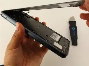
    • Slowly flip the cover over and set it down on top of the rest of the device.

    • Disconnect the fingerprint flex cable using the flat end of a spudger.

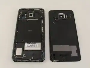
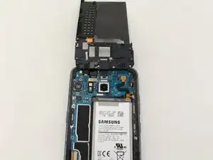
    • Remove the back cover.

    • To reconnect the fingerprint sensor cable during reassembly, angle the back cover until the flex cable lines up over its socket. Use the flat end of a spudger to snap the cable in place by gently pressing straight down.

  7. lNobq2ZYUNKZpxSr
    lNobq2ZYUNKZpxSr
    NaOxZow5oboGstsh
    Lgjfru1pYr2TrmFH
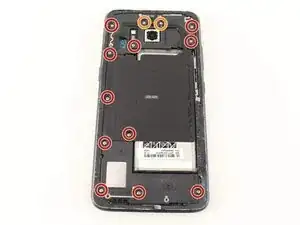
    • Remove eleven 3.5 mm screws using a Phillips #00 Screwdriver.

    • Remove two 2mm screws using a Phillips #00 Screwdriver.

  8. X2yOcgYi32QnVoxB
    X2yOcgYi32QnVoxB
    XfcX1NLKPqZXxFNZ
    • Remove the NFC antenna and charging coil assembly using the flat end of a spudger.

  9. MxUmJ4kGN6sfT6Qd
    MxUmJ4kGN6sfT6Qd
    T4cb4cTNrDg22kGM
    PvaJAKgAA6l3TJvc
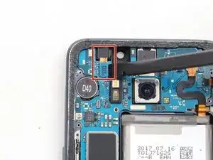
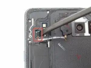
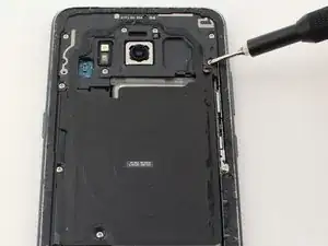
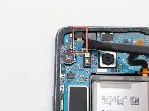
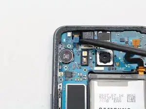
    • Disconnect the iris scanner flex cable from the motherboard using the flat end of a spudger.

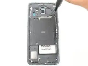
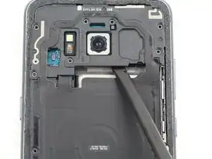
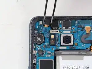
    • Use tweezers to gently lift the iris scanner from its slot.

Conclusion

To reassemble your device, follow these instructions in reverse order.

Erik Mauk

Member since: 24/01/19

1396 Reputation

0 comments