Introduction
If buttons get stuck or you need to make any other type of replacement to the hardware of the video camera, you must first remove the outer case. This guide shows how all of the outer casing is removed, which involves removing extensive amounts of screws. To complete the case disassembly, the audio inputs are also removed from the video camera.
-
-
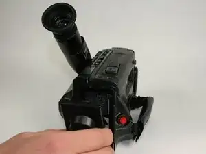
Press the battery release button.
-
While pushing the battery button, slide the battery to the left.
-
-
-
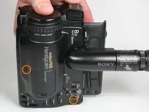
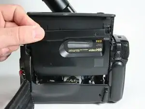
Open the cassette cover.
-
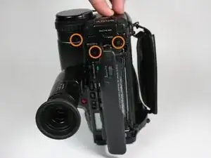
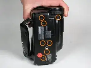
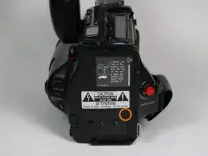
Unscrew 14 screws located on the outer casing. Three are located on the top face 2x6.8mm and 1X4.54mm, three on the left face 1x4.54mm,1x5.3mm and seven on the bottom face 5x4.54mm and 2x6.77mm.
-
-
-
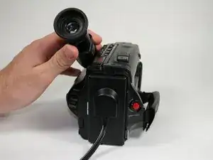
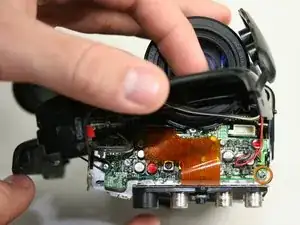
Remove five screws from the right side, from bottom to top, 3x4.54mm 2x5.70mm.
-
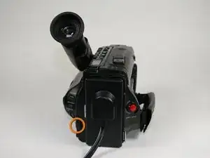
Remove the single 4.5 mm screw from the backside.
-
-
-
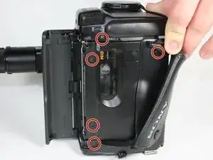
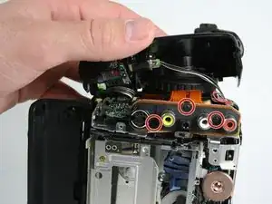
Pull the audio/video inputs underneath the microphone assembly. The inputs should still be connected to the circuit board.
-
-
-
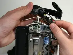
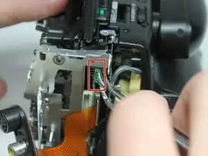
Using metal tweezers, pull out the plastic connector box on the front side.
-
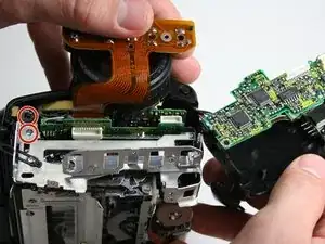
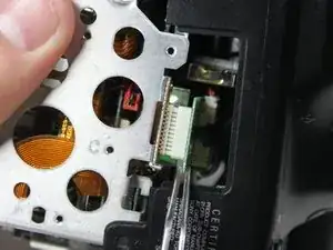
Again use metal tweezers to pull out the connection box on the bottom of the camera. The right side of the case can now be removed by pulling it to the right.
-
To reassemble your device, follow these instructions in reverse order.