Introduction

Use this repair guide to remove and replace the Sony Handycam DCR DVD103 lens.

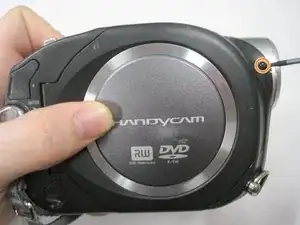
If the Sony Handycam DCR DVD103 has a cracked or broken lens, this repair guide will help the camera perform as designed. This repair does not require special skills.

The camera featured in this repair guide does not contain a battery.

  1. PLTicmKmcCon5OZE
    • Images do not show the camera's battery.

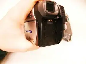
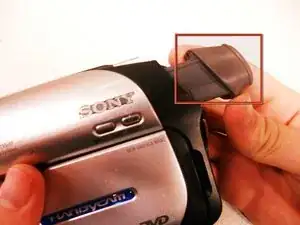
    • On the back of the camera beneath the viewfinder, locate the battery pack.

    • Press the small button.

    • Slide the switch forward.

  2. ULXdphhCbIUAFRJw
    • Remove the battery from the camera.

    • To reinsert the battery, slide the battery into the camera.

  3. dcSN2nErUW5J2CSr
    • Using a #00 Phillips screwdriver, remove the six 4.5 mm screws from the camera's bottom.

  4. vlOZuFtQrAjlp1Sq
    vlOZuFtQrAjlp1Sq
    MBWKrZVpqORP3LVi
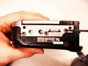
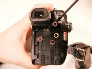
    • Remove the three 4.5 mm screws beneath the battery.

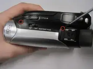
    • Remove the 2.9 mm screw from the right corner.

    • Remove the two 4.5 mm screws from the battery's right wall.

    • Images do not show the battery.

  5. lAPiOvsHTlqcbpOl
    • Remove the 4.5 mm screw under the output flap on the front of the camera below the lens.

  6. cQrLlb5hJQ3LQObO
    cQrLlb5hJQ3LQObO
    l4im6sOFktAPgPax
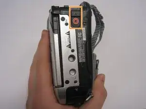
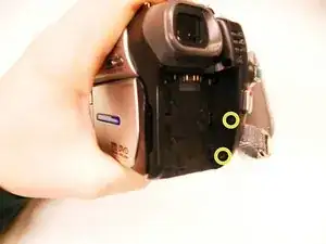
    • Remove the two 4.5 mm screws at the top of the camera.

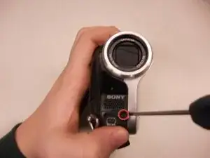
    • Remove the 4.5 mm screw from the disk side of the camera (next to the lens).

  7. wEXYBjwVHZAWASLj
    wEXYBjwVHZAWASLj
    VFXZUwppk5FwUylP
    • Extend the gray viewfinder, then gently remove the black plastic casing.

    • Caution: Plastic pieces are fragile.

  8. QcQfdQamrO2GbyXU
    • Remove the two 2.9 mm screws under the black plastic casing.

  9. KblSqgLgbnPlsqsR
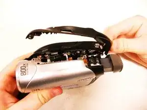
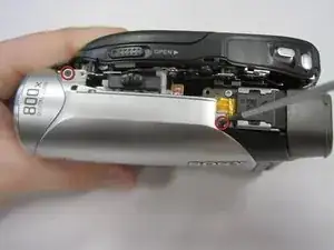
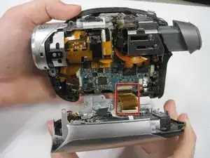
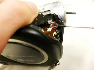
    • Gently pull apart the outer silver case and screen.

    • Remove the copper wire strip to detach the case from the camera.

  10. oQRLDVQRdImurtVa
    • Remove the 4.5 mm thread that connects the lens to the camera body.

  11. ZyKwxMelCujVeaVo
    ZyKwxMelCujVeaVo
    AabcXfS3VpZmKabA
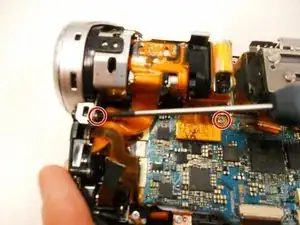
    • Remove the two 4.5 mm screws from the bottom left and top left of the lens casing.

    • Remove the two 2.9 mm screws from the top right and bottom right of the lens casing.

  12. ekLxXH5esXHVVUjI
    • Gently slide the ribbon cables away from their connections on the motherboard.

    • Caution: Too much force will tear the cables.

  13. OFwoG1RRYTkVOkWa
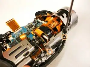
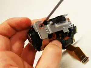
    • Remove the 4.5 mm screw that connects the camera body to the lens on the DVD side of the camera.

  14. KDQGEOGwbQDxFf2E
    KDQGEOGwbQDxFf2E
    EuQvBSCV5NEZyZRD
    2UHc4iXeEbfhuhep
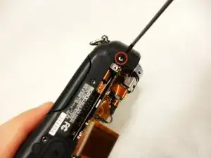
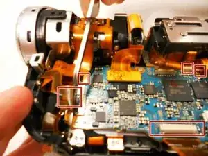
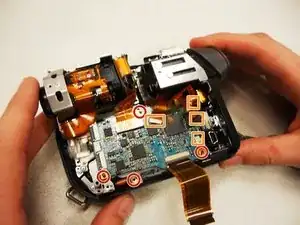
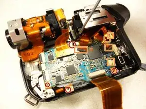
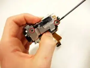
    • Remove the five 2.9 mm screws connected to the circuit board.

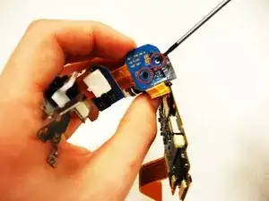
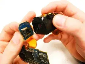
    • Remove the circuit board from the camera.

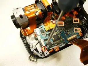
    • Remove the five copper wires attached to the circuit board.

  15. S3ObEkXKFJfmRTv6
    S3ObEkXKFJfmRTv6
    u6AiPecfTYGnwFQZ
    • Unscrew the three 2.9 mm black screws to remove the metal bracket from the lens.

  16. hodI4EApYYOoRt5H
    hodI4EApYYOoRt5H
    SVlhP4MfpNOBNlAj
    • Remove the two silver 4.5 mm screws from the bottom of the lens.

    • Caution: Be careful with the lens once the screws are removed. The lens contains a small piece of glass that can fall out.

Conclusion

To reassemble your device, follow these instructions in reverse order.

kaitlin

Member since: 11/01/11

342 Reputation

0 comments