Introduction
Can't save all those breathtaking moments without an operating SD card slot! This guide will guide you through removing the outer casing and replacing the SD card slot.
-
-
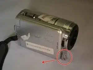
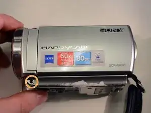
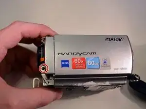
Place device on left side with front lens facing right.
-
Using a JIS size #00 precision Phillips screwdriver, unscrew the left middle 3mm Phillips screw.
-
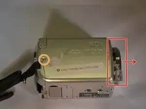
Open the "DC IN" plastic tab (Second 3mm Phillips screw is revealed).
-
Unscrew the second 3mm Phillips screw.
-
-
-
Turn device over onto its top with the front lens facing right.
-
Unscrew the top left and top right 3mm Philips screws.
-
-
-
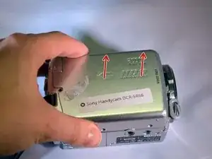
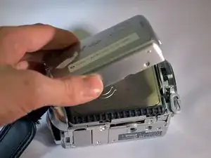
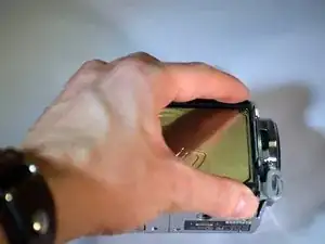
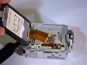
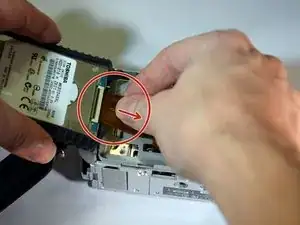
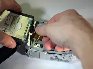
While securely holding the HDD in your left hand, use the soft pad of your right hand fingers to gently pull the ribbon wire out of its socket, toward your right.
-
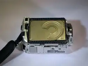
Replace HDD.
-
-
-
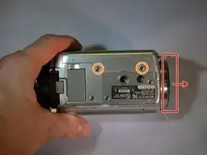
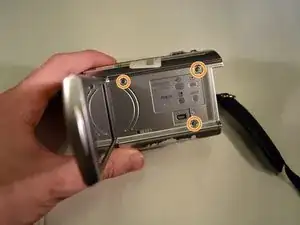
On the bottom of the device, use a JIS size #00 precision Phillips screwdriver to remove the 3mm Philips screws on the right side and middle bottom of the bottom case panel.
-
Remove the bottom case panel.
-
-
-
Lay the device on it's left side, with the front lens facing left (first photo).
-
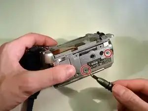
Remove the three visible 3mm Philips screws with the Phillips precision screwdriver (see 2nd photo).
-
-
-
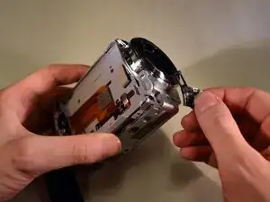
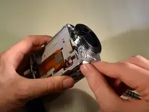
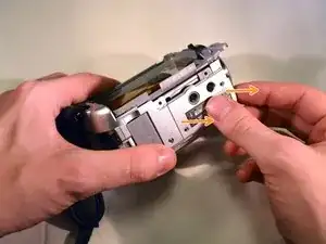
Hold the device securely in your left hand with the front lens facing right.
-
Remove the two black 3mm Philips screws with the screwdriver.
-
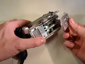
Remove the grey tray by carefully lifting it out.
-
-
-
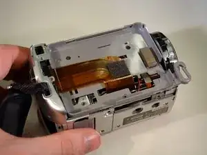
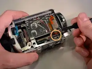
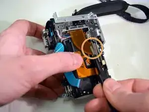
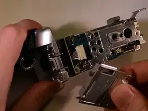
Using the pointed black spudger, carefully open the little black clasp on the large ribbon wire port.
-
-
-
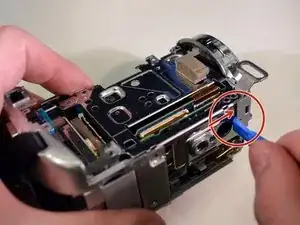
Use the blunt tweezers to unplug the red and black wire by pulling out and away./Provide a better close up of the picture.
-
Gently unplug the small ribbon wire./Provide a better close up of the picture.
-
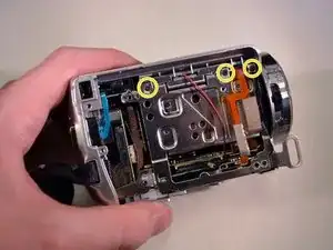
Unscrew the top three 3mm Philips screws with the Phillips precision screwdriver. /Unscrew the top three 3mm Phillips screws with the Phillips precision screwdriver./Provide a better close up for this picture.
-
-
-
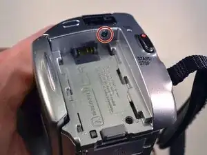
On the back of the device, remove the top black 3mm Philips screw with the Phillips precision screwdriver./On the back of the device, remove the top black 3mm Philips screw with the Phillips precision screwdriver.
-
-
-
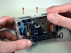
Remove the top case panel of the device by lifting up and away./Edits are unnecessary for this step.
-
Set the top case panel aside./Set the device aside.
-
-
-
On the top of the device, unscrew the right 3mm Philips screw with the Phillips precision screwdriver/Get a close up of the screw in this picture.
-
On the left side of the device, unscrew the bottom left 3mm Philips screw wit the screwdriver./Same thing with this picture. A close of the screw would help readers.
-
-
-
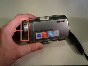
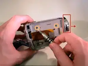
Set the device facing forward, with its bottom down.
-
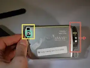
While securing the device with your left hand, use gentle rightward pressure with a plastic opening tool to pop off the shutter assembly. To do this, position the plastic opening tool in the slot labeled in photo one. A close up of the shutter assembly in the picture might help also.
-
-
-
On the left side of the device (with the front lens facing left), unscrew the left middle 3mm Philips screw with the screwdriver./A close up of the screw in the picture would be better.
-
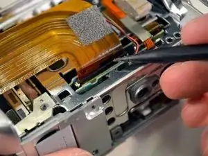
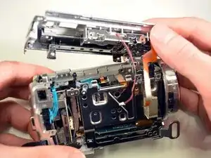
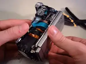
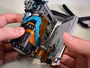
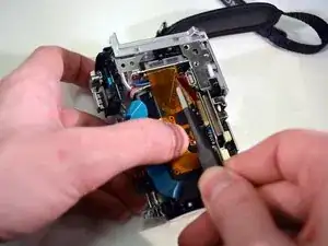
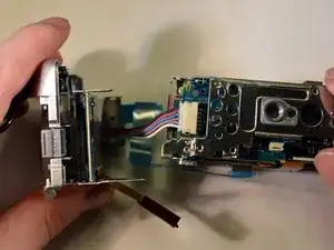
Carefully pivot the dismantled piece of the device until the ribbon wires are fully exposed./Carefully pivot the dismantled piece of the device until the ribbon wires are fully exposed.
-
-
-
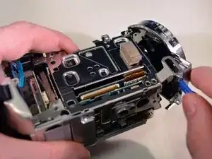
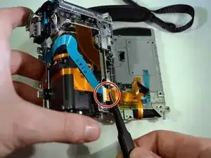
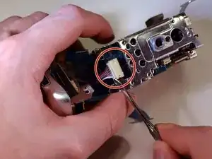
Use the blunt tweezers to unplug the small orange ribbon wire./No edits necessary.
-
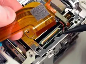
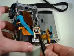
Use the same tweezers to unplug the small white ribbon wire./Make a close up of the small white ribbon wire in this picture.
-
Set the left side of the device in a secure place.
-
-
-
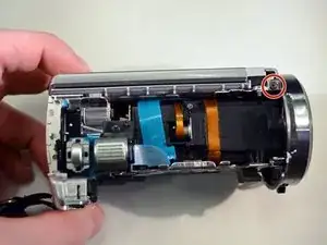
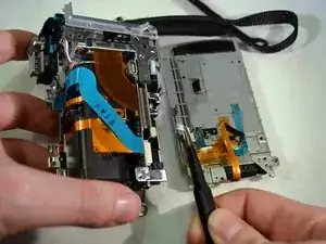
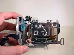
Use the blunt tweezers to unplug the blue ribbon wire./No edits necessary.
-
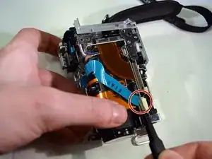
Unplug the orange ribbon wire./no edits necessary.
-
-
-
Follow steps 1-14 for the Lens replacement./Follow steps 1-14 for the lens replacement.
-
Remove the bottom left 3mm Philips screw./Make a close up of the screw for this picture.
-
-
-
On the bottom of the device, remove the last 3mm Philips screw on the last panel./Make a close up of the screw for this picture.
-
Remove the panel./No edits necessary.
-
-
-
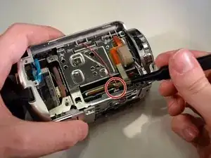
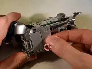
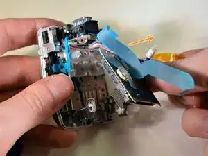
Use a pointed metal spudger to pop the plug out of the socket./Make a close up of this plug in this picture.
-
-
-
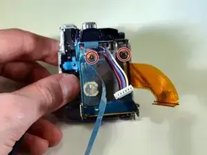
Unscrew the two brass 3mm Philips screws with the screwdriver. /Make this picture a close up.
-
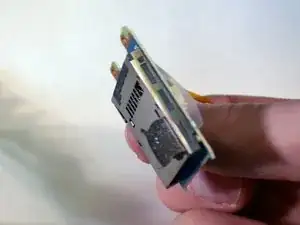
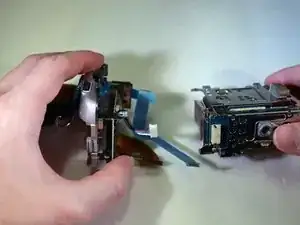
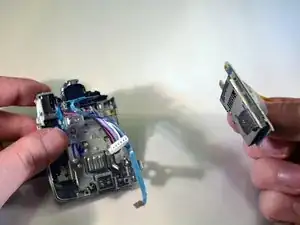
Carefully remove the SD card slot, once it's unfastened.
-
The SD card slot is now removed as shown in photo three.
-

To reassemble your device, follow these instructions in reverse order in addition to the Lens Replacement Guide.