Introduction
-
-
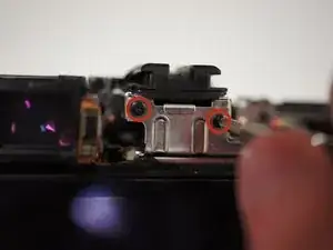
Remove the two 3/32" #00 screws located next to the viewfinder using the Phillips #00 screwdriver.
-
-
-
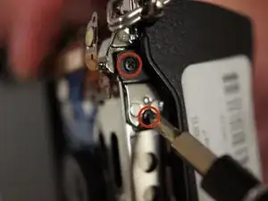
Remove the two 5/32" #00 screws from the right side of the camera below the D ring using the Phillips #00 screwdriver.
-
-
-
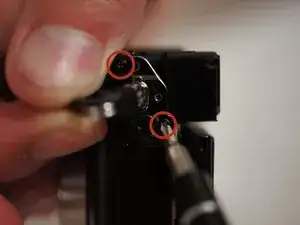
Remove two more 3/32" #00 screws from the bottom of the camera using the Phillips #00 screwdriver.
-
-
-
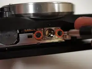
Remove two more 3/32" #00 screws from the metal bracket on the left side of the camera using the Phillips #00 screwdriver.
-
-
-
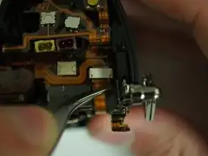
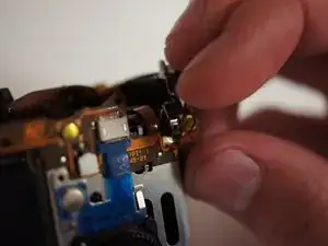
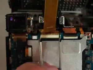
Unplug the orange ribbon cable on the top right of the camera next to the metal bracket by applying tweezers to the tabs on either side of the plug.
-
-
-
Before pulling off the assembly, fold the rightmost tab of the flexible circuit board away from the metal bracket.
-
-
-
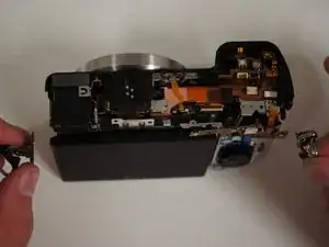
Pull on the D rings on either side of the camera to start removing the assembly.
-
Once the brackets are cleared from black shell, take them off and set them aside.
-
Continue to remove the screen assembly.
-
-
-
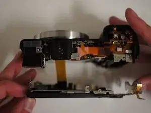
With the camera face down, move the assembly away from you to get a clear view of the wide ribbon cable.
-
Unplug the cable by applying tweezers to the tabs on either side of the plug.
-
Set the LCD assembly aside.
-
To reassemble your device, follow these instructions in reverse order.