Introduction
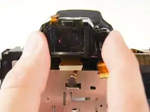
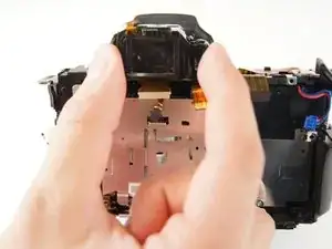
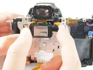
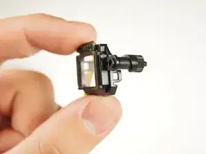
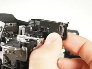
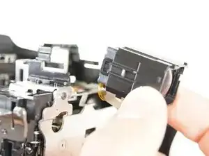
When replacing the viewfinder, there are two separate components to detach. First, the eyepiece sensor needs to be removed before the viewfinder can be detached and replaced. The viewfinder will pop out from its slot by using your fingers to wiggle the part around.
-
-
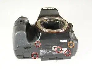
Unscrew the four 4.0 mm Phillips #00 screws with a on the base of the camera below the the scheme that separates the front and back panels.
-
Unscrew the 5.0 mm Phillips #00 screw on the bottom right of the camera.
-
-
-
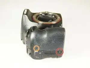
Unscrew the 4.0 mm Phillips #00 screw on bottom of the left side of the camera.
-
Unscrew the 5.0 mm Phillips #00 screw near the top of the left side of the camera.
-
-
-
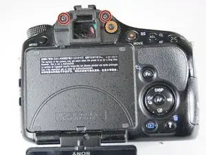
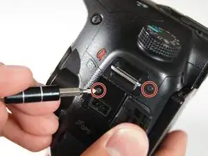
Unscrew the two 4.0 mm Phillips #00 screw at the top of the camera by the eyepiece.
-
Unscrew the 5.0 mm Phillips #00 screw of the dial below the other two screws.
-
Once all the screws are removed, carefully use your hands to detach the back panel from the camera. Working around the edges can help as well.
-
-
-
Remove the two 4.0 mm Phillips #00 screws on the right of the camera that are located on the upper right side and under the "Remote" port flap.
-
Detach the right side panel with the remote and HDMI ports of the camera by gently pulling on the panel.
-
-
-
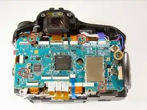
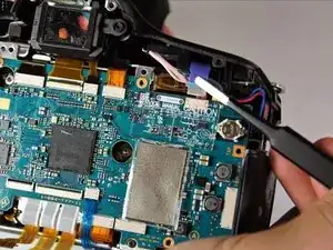
Use tweezers to remove the blue and orange ribbon connectors from their connection points pictured here.
-
-
-
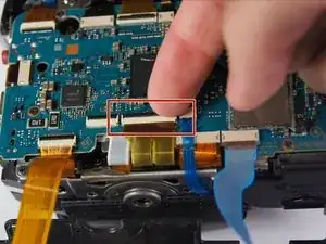
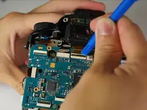
Use your finger to flip the switch that holds the dual ribbon connector in place.
-
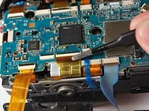
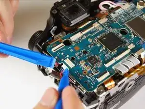
Gently use tweezers to disconnect the dual ribbon connector and the thin blue ribbon connector to the right of it from the circuit board.
-
-
-
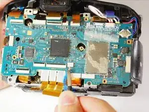
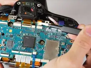
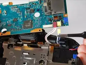
Use tweezers to disconnect the blue, gold, and brown ribbon connectors near the top of the camera.
-
-
-
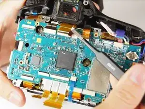
Use a plastic opening tool to pop open the connector holding the next ribbon to the circuit board.
-
Use tweezers to disconnect the ribbon.
-
-
-
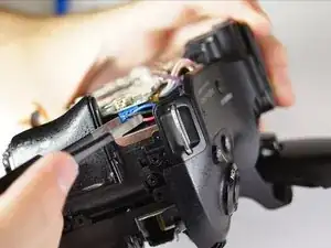
Use either plastic opening tools or tweezers to unplug the white adapter located on the right side of the circuit board.
-
-
-
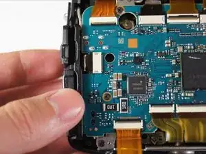
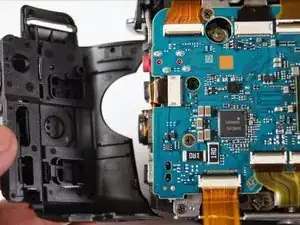
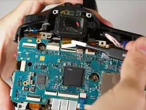
Gently lift the circuit board away from the camera and turn it over.
-
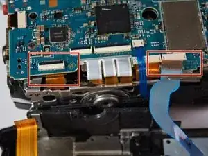
Use tweezers to disconnect the final two plugs and completely remove the circuit board from the camera.
-
To reassemble your device, follow these instructions in reverse order.