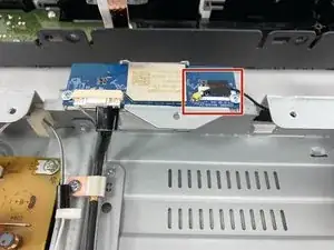
Introduction
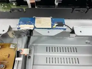
This part connects the device to the internet so that it can receive software updates from Sony and so that the owner can access their desired streaming services and use the Blu ray player as multi-media device,
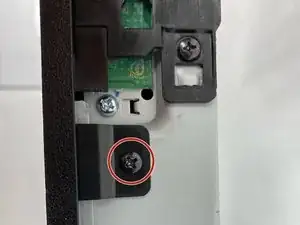
Please follow the top cover and front panel removal as this card is located right under the both those panels in the center of the device.
-
-
Use a Phillips #2 screwdriver to remove the two 10.5 mm screws that secure the two side panels onto the back of the player.
-
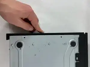
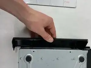
Slide both covers back about a 1/2 inch, then pull them away from the case.
-
-
-
Use a Phillips #2 screwdriver to remove the two 10.5 mm screws on the side of the case, each connecting to a tab on the cover.
-
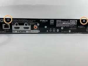
Use a Phillips #2 screwdriver to remove the two 10.5 mm screws (one next to the Wi-Fi logo and one next to the Blu-ray logo).
-
-
-
Press in the tabs found on the front-sides of the case (connected to the front panel).
-
Slide the top cover forward.
-
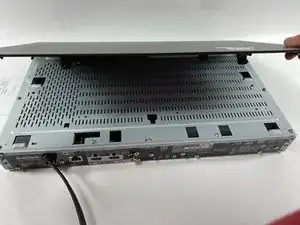
Lift off the case.
-
-
-
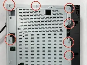
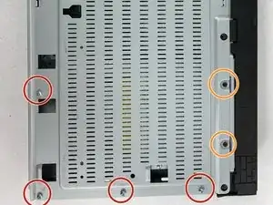
Find the eleven 10.5 mm silver screws and two 6 mm black screws on the perimeter of the silver cover plate.
-
Remove the silver screws using a Phillips #2 screwdriver and the black ones using a Phillips #1 screwdriver.
-
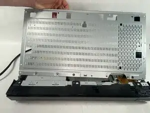
Life the back of the cover up and off of the chasis.
-
-
-
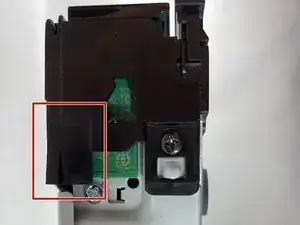
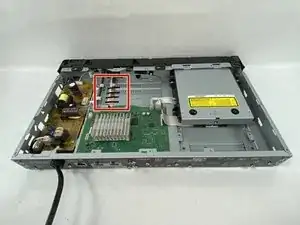
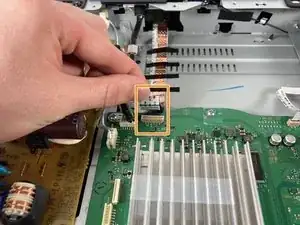
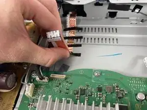
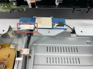
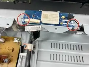
Toward the panel there is a ribbon cable with 4 small black pieces of tape holding it down
-
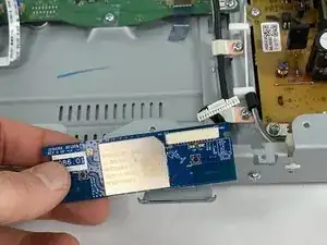
Pull directly up on the ribbon cable to disconnect it from the motherboard
-
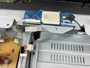
Gently pull the cable back away from the motherboard pulling the tape off with it
-
-
-
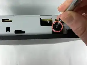
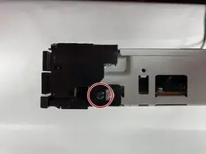
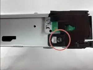
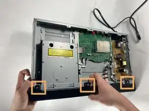
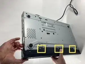
There are screws on every side of the front panel holding it in. Use a #2 Phillips head screwdriver to remove the nine screws.
-
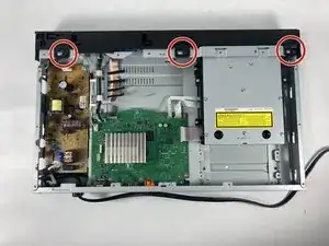
Unscrew the three 10.5 mm long ph #2 screws on the top.
-
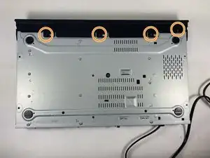
Unscrew the four 10.5 mm long ph #2 screws on the bottom.
-
-
-
Lift tab on the left side of the device
-
Work your way right, lifting the next tabs. One on the bottom and one the Top
-
Continue working the tabs on the top and bottom, keeping them from snapping back in place.
-
-
-
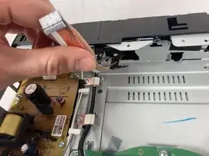
Remove the gold-colored connection, remove the tape, and pull it off using the wire. Be gentle because the wire is very small as is the connection.
-


To reassemble your device, follow these instructions in reverse order.