Introduction
This guide aims to help fixing ripped out or damaged cable that connects from USB to chatmix.
-
-
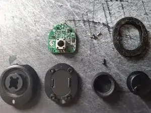
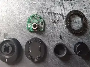
To begin, unplug anything chatmix is connected to - headset, and the PC. Flip the chatmix around to the back and remove the glued rubberized oval foot (Top right part on the image)
-
Once the oval foot is removed, You will find four small hex screws. Remove these with a screwdriver. Be careful as they are very easy to strip.
-
-
-
To further disassemble the chatmix - remove the rubberized grooved cover of the knob. The easiest way is to stick something pointy - like a screwdriver, into the top part and pry the rubber part off the knob.
-
Once the rubber is removed, You will be left with the plastic part for the knob. You'll find an opening with a black hex screw inside. - Unscrew it and then the pcb should come loose.
-
-
-
Once you have finished taking it apart, you should have 4 base screws, 1 knob screw, top and bottom housing, knob and the rubber cover as well as the oval foot.
-
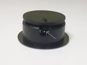
Take the PCB and flip it around, so the knob encoder is facing the other direction. The PCB wont sit flat. You may find a black cover over the solder joints near the base on the opposite end of the pcb from where the headphone connects into.
-
Manually remove the black sticky substance over the solder joints. I don't know if heating helps, having gently scraping it off using a pocket knife and my fingers - but a screwdriver would do. Be careful while scraping it off, to not damage any other parts on the PCB.
-
-
-
Now that You have uncovered the solder joints on the back side, You are ready to begin the soldering process. Plug in Your solder iron and let it heat up.
-
To resolder the cable back into the chatmix I recommend using already existing solder joints.
-
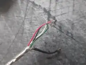
Inside your USB cable that connects to the chatmix, You will have 5 internal cables. It consists of standard USB 4 pinout: - Green (D+), White (D-), Red (+5V), Black (Ground)and an additional thicker black cable that wraps around the other four.
-
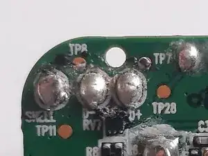
Looking at the PCB Photos. On the photo of the left side You will find 3 solder joints. Starting from the left You will find: Shell - solder in the extra thick black cable, D- - for the thin white cable, D+ - for the thin green cable.
-
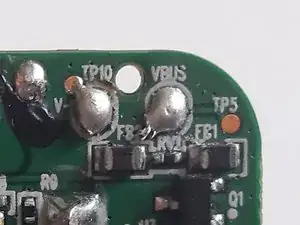
Now look at the right side of the PCB. You will find, going from the right, 2 solder joints: VBUS - for the Red (+5V) cable and V- (for Ground)
-
Begin soldering the cables to their designated joints. Try to keep the usb cable going outwards of the pcb to later be able to easily reassemble the chatmix.
-
-
-
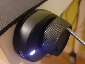
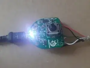
Once Youre finished soldering the cables back in, Plug in the chatmix into the computer and Your Arctis headset. Verify that audio aswell as the microphone works correctly.
-
Once You have verified that chatmix works as it should, reassemble the chatmix carefully in the reverse order to how you've taken it apart.
-
Remember to cover up the exposed wire in insulating tape or cable shrink wrap.
-
And Youre done!
-
One comment
J'm'assois !
Nevetso -