
Introduction
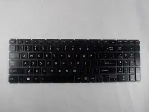
If your Toshiba Satellite P55W-C5200X keyboard is not responding it may be time for a replacement. Keyboards may become unresponsive if there is a build up of dirt or other materials in the keys. If not it may be a more severe problem and would require a full replacement of the keyboard itself.
The tools needed to gain access to the keyboard are listed below . This is a low risk operation, the only requirement for safety is to make sure the device is turned off before starting and keeping away from liquids while working on the device.
This guide will tell Toshiba Satellite P55W-C5200X users how to replace a defective keyboard.
-
-
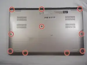
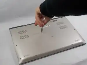
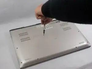
Use the Phillips #00 screwdriver to remove the ten 4.0 mm screws located at the bottom of the laptop.
-
-
-
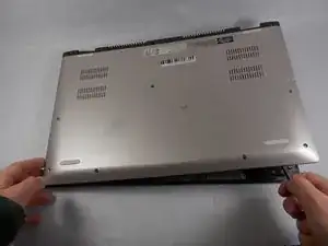
Use the black nylon spudger to pry the back casing along the edges.
-
Continue to pry along the edge of the back case until the back is ready to be removed.
-
-
-
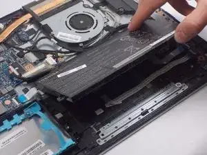
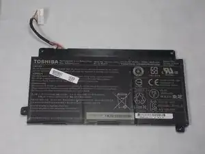
Disconnect the battery cable from the motherboard by carefully pulling on the black wire at the point closest to the white tab.
-
-
-
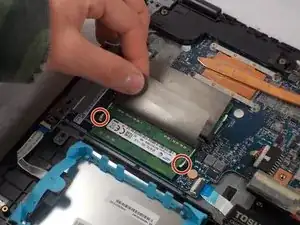
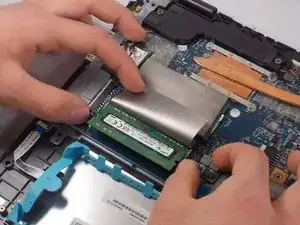
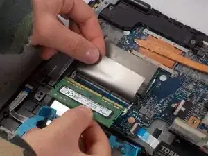
There are two metal brackets holding each RAM stick in place. Carefully move the metal brackets outward on both sides at the same time.
-
Pull the RAM sticks out.
-
-
-
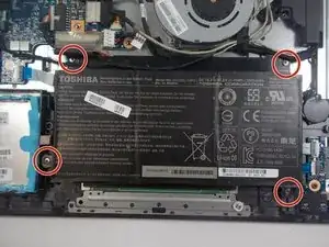
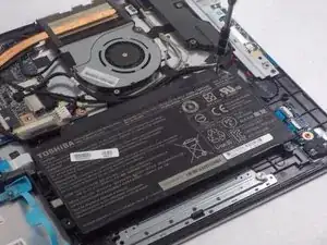
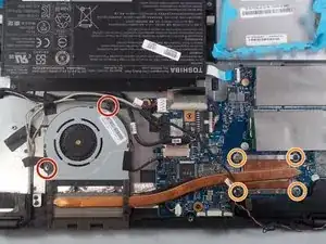
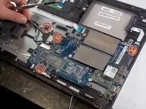
Remove the two 4.0 mm screws using the Phillips #00 screwdriver.
-
Remove the four 2.0 mm screws using the Phillips #0 screwdriver.
-
-
-
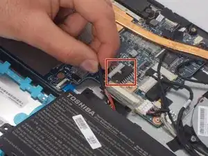
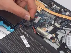
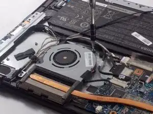
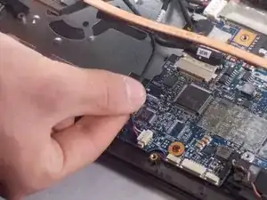
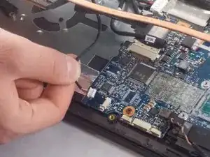
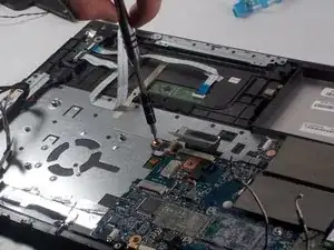
Disconnect the fan cable from the motherboard by carefully pulling on the black wire at the point closest to the white tab.
-
-
-
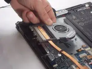
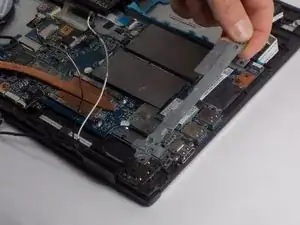
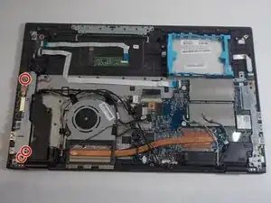
Once the fan, ram, and battery are removed, remove the motherboard.
-
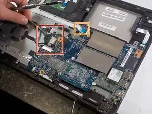
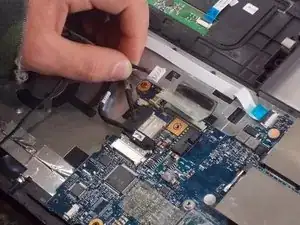
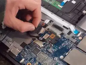
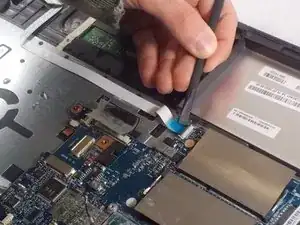
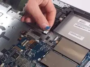
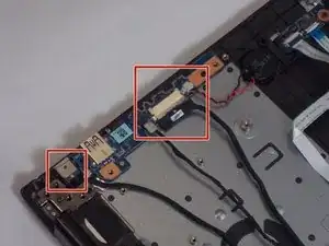
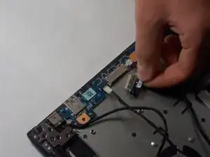
Detach the three connecting wires.
-
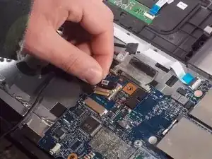
Remove the white, blue-tipped cable ribbon too.
-
-
-
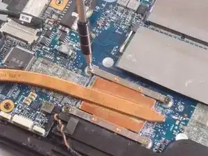
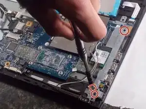
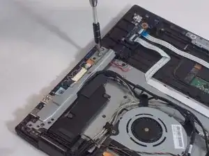
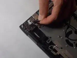
Use the Phillips #00 screwdriver to remove the three 5.0 mm screws that are holding the metal bracket in place.
-
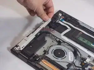
Gently remove the metal bracket.
-
-
-
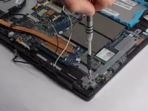
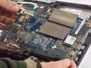
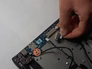
Use the Phillips #00 to remove the four 8.0 mm screws that are holding the motherboard in place.
-
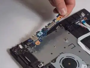
After removing all the screws, gently remove the motherboard.
-
-
-
Similar to step 4, there is a metal bracket that must be removed to get to some ports.
-
Use the Phillips #00 screwdriver to remove the three 5.0 mm screws that are holding the metal plate in place.
-
Gently remove the metal bracket off the ports underneath.
-
-
-
Once the connecting wires are removed, remove the 8.0 mm screw of the USB ports, using the Phillips #00 screwdriver.
-
Gently remove the USB ports.
-
-
-
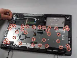
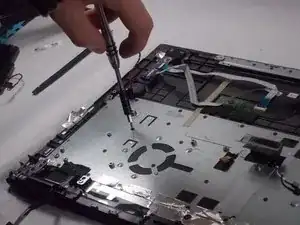
Remove the thirty-three 1.0 mm screws with the Phillips Head #000.
-
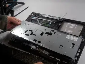
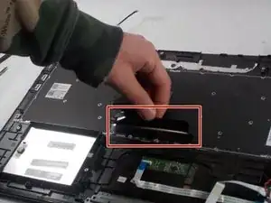
Gently remove the metal cover.
-
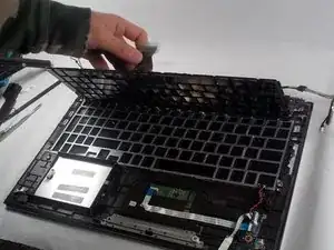
To reassemble your device, follow these instructions in reverse order.