Introduction

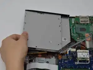
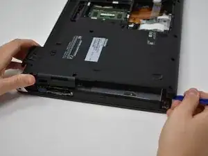
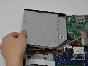
The optical drive is a relatively simple replacement. It must also be removed to access the keyboard.

  1. LNCGZVxeBoVNoFoW
    LNCGZVxeBoVNoFoW
    rJiQ3F5lUjeSAxVY
    • Slide lock 1, located on the right side, to the unlocked position.

  2. rpETiEUPXW1donHF
    rpETiEUPXW1donHF
    VKGD3NoUN6kDLLEc
    • While holding lock 2 (left side) in the unlocked position, pull out the battery pack.

    • It is not necessary to hold open lock 2 for re-installation.

  3. tDosIEHShAyYB2HR
    tDosIEHShAyYB2HR
    eqot1TwLTCGYiMS2
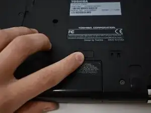
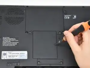
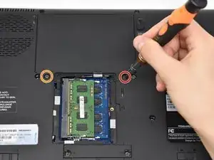
    • Unscrew the single screw on the RAM access panel using a Phillips #0 screwdriver.

    • The screw will not come apart from the panel.

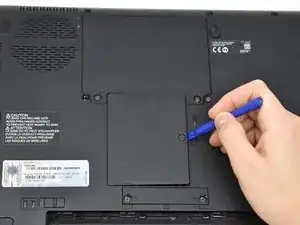
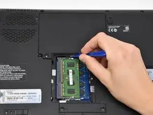
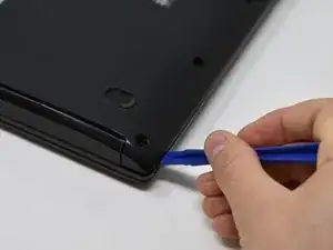
    • Use a plastic opening tool to pry off the access panel.

  4. ap2TVFSchLjW1erw
    ap2TVFSchLjW1erw
    6EAJReTbugCHZcuR
    • Remove the 11 mm screw from the right side of the hard drive access panel using a Phillips #0 screwdriver.

    • Remove the 3.5 mm screw from the left side of the access panel using a Phillips #0 screwdriver.

    • Use a plastic opening tool to pry off the access panel from the bottom.

  5. 4JnJtileYLucCqhR
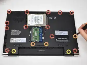
    • Remove twelve 5.5 mm screws from the main back cover using a Phillips #0 screwdriver.

    • Remove three 11 mm screws from main back cover and mini access panel using a Phillips #0 screwdriver.

    • Remove two 9.5 mm screws from the main back cover using a Phillips #0 screwdriver.

    The lower two orange screws are definitely not 11mm - that would prevent the keyboard re-seating, as I discovered.

    I suggest 5.5mm. A cover is shown between them; - my R940 (and virtually identical R840) has lost that.

    Underneath it is a docking connector.

    I have a working R940 & R840, but also a few other R840 in only slight distress (screen hinge screws, a couple missing SATA connector).

    So while I might not be able to tell now where those misplaced 11mm screws should go, I will be able to inspect the other untouched ones, and update this note.

    Ross Matheson -

  6. MpPFVcemCbfQRQPx
    MpPFVcemCbfQRQPx
    adEoQYYkLgYMfY12
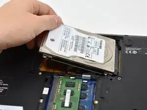
    • Lift the hard drive out of the access panel.

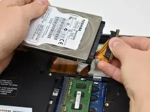
    • Disconnect the SATA connector from the hard drive by pulling straight out.

  7. 1rKgXIMRDVWZOhhp
    1rKgXIMRDVWZOhhp
    yZmZlW31bOwWsQxN
    • Insert the plastic opening tool into the edge of the laptop and pry off the back cover.

  8. lQ4TWl436GQSfU4d
    • Remove two 2.5 mm screws from the side of the optical drive using a Phillips #0 screwdriver.

  9. rNxpAPBA2FINYPNR
    • Lift up the bracket covering the connector.

    • This bracket should not be fully removed from the optical drive.

  10. rQgBHtVgUNHNphY2
    • Gently remove the SATA connector from the port.

  11. ciykctqPCBLBa6CG
    • Gently lift the optical drive out.

Conclusion

To reassemble your device, follow these instructions in reverse order.

Holly Strauch

Member since: 23/09/18

409 Reputation

0 comments