Introduction

If your speakers keep cutting out or are no longer working at all, you will follow this guide to replace them. Beyond just being screwed down the speakers are also glued into place and must be torn/pulled off in order to access. Soldering is also required to remove from motherboard, so use caution.

  1. KNlCHtlvU1d4Tose
    KNlCHtlvU1d4Tose
    XAtLFMVfePNeWYGE
    UiRG6lbmCEbOiQdA
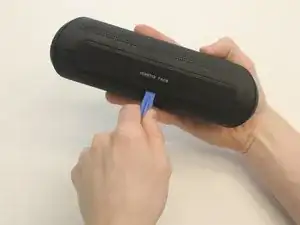
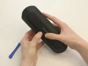
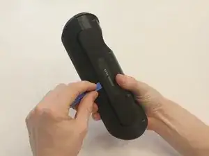
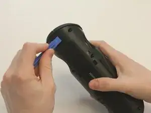
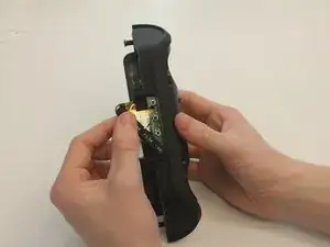
    • Starting with the Taco on its side, use the plastic opening tool to pop off the outer casing near the base.

    • The base labeled "VENSTAR TACO" is glued. Be careful separating the two sides of the device.

  2. hpoEpGScZiTFZlRw
    hpoEpGScZiTFZlRw
    rCMBbALBXDQWs6rJ
    • Repeat the previous step on the opposite side to remove the other outer casing.

  3. aHQ24ec3SVFJPkqh
    aHQ24ec3SVFJPkqh
    jwtBYlBgb2bZXY6D
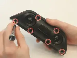
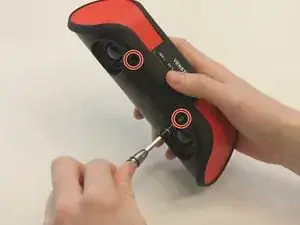
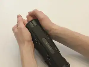
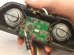
    • Using a Phillips PH0 3 mm-bit screwdriver, remove the six screws on the inner layer of the Taco.

    • The screws are small and can get stuck. Use tweezers to pull them out if you are having trouble.

  4. IbXgXRSEPVZGKP2x
    IbXgXRSEPVZGKP2x
    yFLponY6ZGZaj2YE
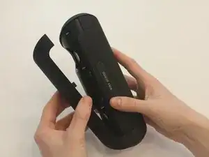
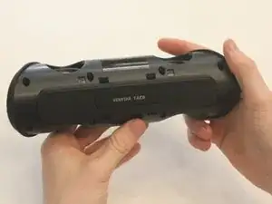
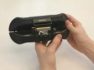
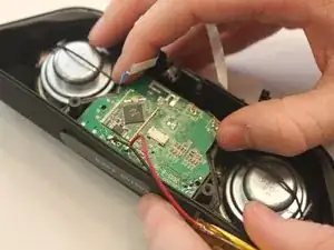
    • From the same side you just unscrewed, use a plastic opening tool to unwedge the inner cover on both sides of the base.

  5. MHQxMZYkP3MSvsYf
    MHQxMZYkP3MSvsYf
    VWVMJbTqlswWyDME
    • Slide off the inner cover. It pulls apart and is held on by a small amount of glue.

  6. lcJLCwyG15hdEejr
    • Remove the rubber covering from the buttons.

  7. RWaohVWO6V4ykOBH
    RWaohVWO6V4ykOBH
    2KwWAbRMLXNSappt
    aSIV3MPiMrkZlkIW
    • Remove the black fabric covering the logic board.

  8. iLyrJaVRgRXnAhNe
    iLyrJaVRgRXnAhNe
    CwT2t5YnSEGxPOfB
    • Move the battery out of the way of the connector.

  9. HtE44GjqxhuamYuu
    HtE44GjqxhuamYuu
    qGxhgkhmLDJ2BKAJ
    • Undo the connector of the flat white ribbon between the switches and the logic board.

  10. TceEgsPWUiSd5gR3
    • Undo the two black 3mm screws on the logic board using the PH0 screwdriver.

  11. BEsADMZkMUcyGRNl
    BEsADMZkMUcyGRNl
    jChI3cPm6JwBSXgi
    HTS6sUiQysmVllDn
    • Gently pull out the logic board.

    • Note that the battery and the logic board are connected and must be removed together.

  12. 3KUjP5LpHRTHw6cM
    3KUjP5LpHRTHw6cM
    UkRtONLSSIkXYHYq
    • Using the Ph1 screwdriver, unscrew both of the 2.5mm screws on either side of the speakers.

    • The screws are glued in and may require the curved tweezers to pull all the way out.

  13. wgJS3KR3DNQQ2BHt
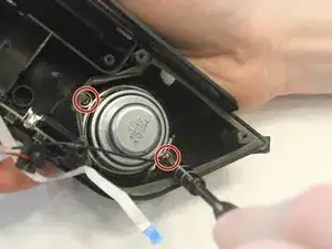
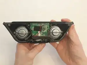
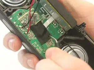
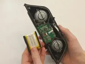
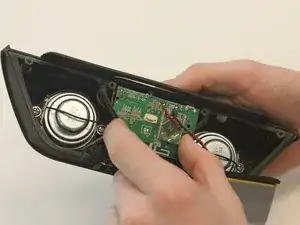
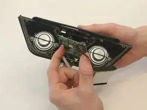
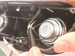
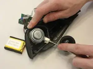
    • Using a metal spudger, carefully wedge out the speakers from the casing.

    • Repeat this step for the removal of the other speaker.

    • Speakers are glued into the casing beyond being screwed and require some care to remove.

  14. PY4ZBN4rahBmKVGH
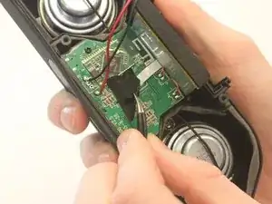
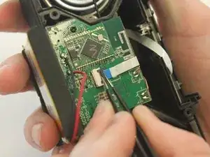
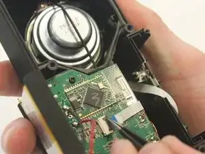
    • Using a portable soldering iron, melt the solder on the black speaker wires on the logic board.

    • Soldering uses hot metal and can burn you!

Conclusion

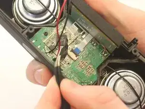
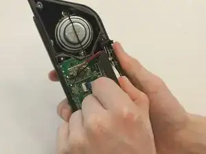
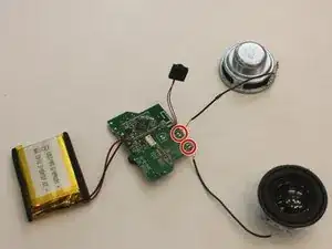
Solder your replacement speakers back to mother board, then to reassemble your device, follow these instructions in reverse order.

Kaylee Simms

Member since: 31/01/16

310 Reputation

0 comments