Introduction

Follow this guide to replace one or both eye tubes on a Valve Index VR headset.

Power off and unplug your Index before you begin your repair.

Note: this is a cumbersome repair with small, loose components that may fall out during the process. Work slow, and carefully keep track of any pieces that fall out.

  1. HS44Zki51H2VDFW2
    • Twist the eye tube relief knob clockwise to fully extend it.

  2. tOH1gFNEuMpQDJKT
    tOH1gFNEuMpQDJKT
    VByiidwDNcbUPiNY
    • Use your hand to gently pull the face gasket straight off of the headset.

    • The face gasket is held in place by four magnets that secure to screws in the face bezel.

    • Before installing a face gasket, ensure the four screws securing the face gasket bezel are installed. Otherwise, the face gasket will not stay in place.

  3. 1v6MrVGCDlfnwSvr
    1v6MrVGCDlfnwSvr
    MXEwSPXLipDlNVW3
    JJT5GCa1x3DyNCGT
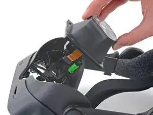
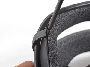
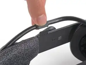
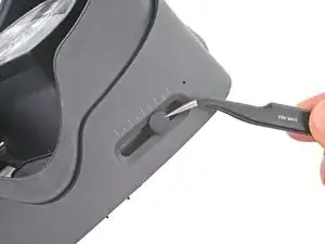
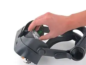
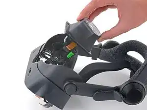
    • Insert the flat end of a spudger in between the bottom of the head strap clip and the head strap padding.

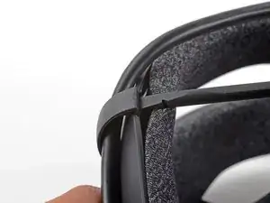
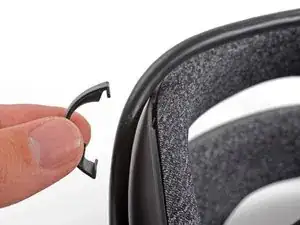
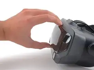
    • Pry up on the head strap clip until it is unclipped from the head strap.

    • To reinstall, first locate the recesses on the head strap for mounting the clip. Next, align the clip with the recesses, verify the tether cable is threaded through the clip, then simply press the clip back into place.

    Do you sell replacement clips?

    TomCatT -

  4. 3aROd5KcPVsfPHKy
    3aROd5KcPVsfPHKy
    Cf2N1rWE4wenPNiQ
    • Use your fingers to pull the tether cable straight up off of the head strap cable guide.

  5. JJTEad1WoMc4RpTY
    JJTEad1WoMc4RpTY
    DdAuAjCk1RrBQRIH
    • Pull the tether cable straight back out of the headset.

  6. Q6vnPQLACExUJPAm
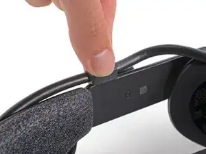
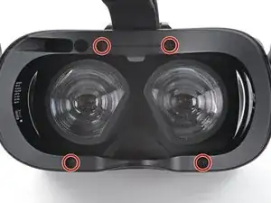
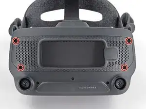
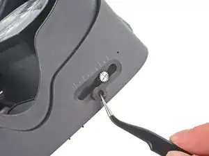
    • Use a T5 Torx screwdriver to remove the four 6.0 mm screws securing the face gasket bezel to the headset.

  7. iwWfpKIFsvfVkEtO
    iwWfpKIFsvfVkEtO
    bVgrOVqS1rQCfvuh
    • Do not try and pry the face gasket bezel off, or you will damage the headset.

    • Grab the left edge of the face gasket bezel with your hand and slide it off of the headset.

    • During reassembly, visually verify the clips on the face gasket bezel are aligned with the headset before sliding it into place.

    This was a little tricky. There's a latching mechanism inside the bezel that requires squeezing the sides a bit to unlatch. In exactly the same hand position as the photo, you need to squeeze. Absolutely don't pry it off or it will snap.

    Scyntrian -

  8. sEjc5DiZuDrNKQvm
    sEjc5DiZuDrNKQvm
    ge3npSLPOFEHemeC
    AJyBuvsEFM4GKU44
    • Repeat the previous step for the right side of the face gasket bezel.

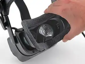
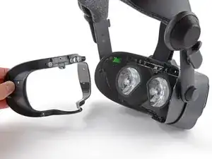
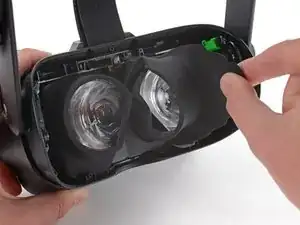
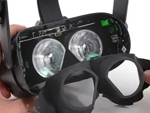
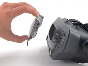
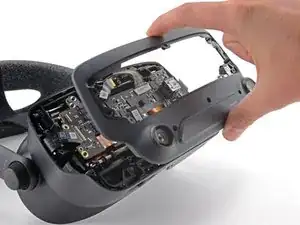
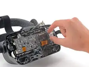
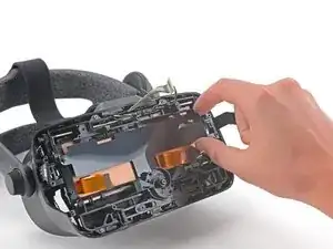
    • Remove the face gasket bezel.

  9. NMNT3GayeVRqcRux
    NMNT3GayeVRqcRux
    54KSAbUUKKPPHXLZ
    PPcM5oL3OWn4IqAN
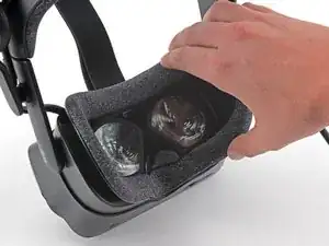
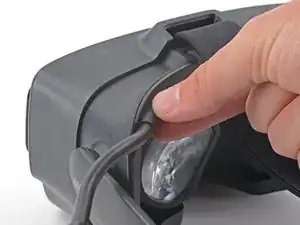
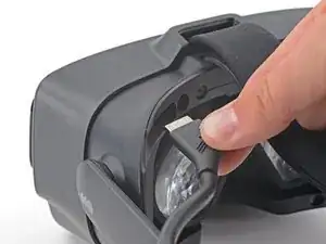
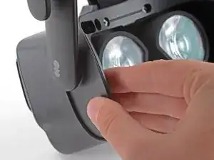
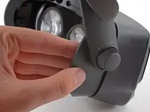
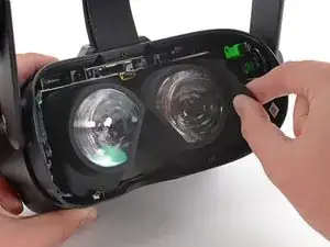
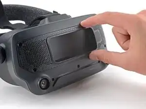
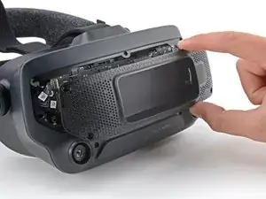
    • Use a pair of tweezers to separate the left edge of the eye tube gasket from the headset.

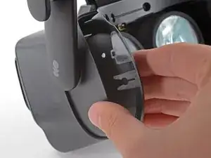
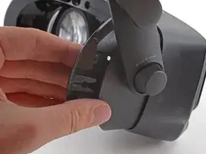
    • Repeat the process for the right edge of the gasket.

    • During reassembly, make sure these holes are secured to the pegs on the headset before continuing.

  10. kTVsVRUUI63foZYS
    kTVsVRUUI63foZYS
    oOlEQODliClA4Tuf
    BJiyQgNTgoFPWJAw
    • Gently peel the eye tube gasket out of the headset.

    • The eye tube gasket is lightly adhered to the perimeter of the lenses. It should pull off easily.

  11. 1VdRVHbgDKg16Aqu
    1VdRVHbgDKg16Aqu
    qILHYgyRBRdTLyRr
    • Use your hand to pull the front cover straight off of the front of the headset.

    • The front cover is held in place by four magnets that secure to screws in the motherboard cover.

    • Before installing a front cover, ensure the four screws securing the motherboard cover are installed. Otherwise, the front cover will not stay in place.

  12. rLSklgCaPuv64Y33
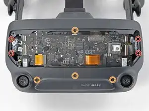
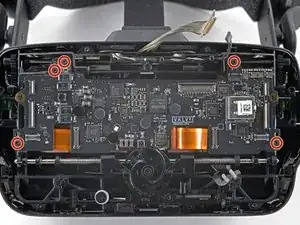
    • Use a T5 Torx screwdriver to remove the four 5.4 mm screws securing the motherboard cover to the headset.

  13. Q4QcJ1kjGYlt1WQO
    Q4QcJ1kjGYlt1WQO
    FeHLfkPY3IgFXAei
    • Remove the motherboard cover from the headset.

  14. yfabmjgyKaEecBt1
    • Use a T5 Torx screwdriver to remove the following eight screws from the front fascia:

    • Four 6.3 mm screws with fine threads

    • Four 6.0 mm screws with coarse threads

  15. 6WcehUioswbZLFC4
    6WcehUioswbZLFC4
    di4NQCposKBIYavu
    yoBJpHU1h3iXSth3
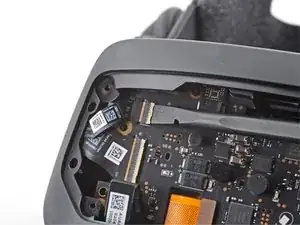
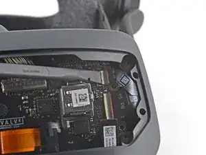
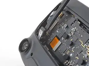
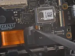
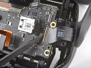
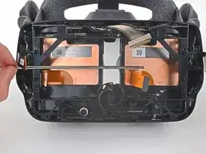
    • Use a spudger to unlock the ZIF connector at the top-left corner of the motherboard.

    • Disconnect the FPC ribbon cable from the motherboard.

  16. 5sstq4o1VF3DSeqJ
    5sstq4o1VF3DSeqJ
    Qnuk1vnMMrFpbfPI
    bmVQZngjLshAgrD6
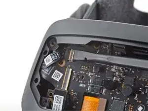
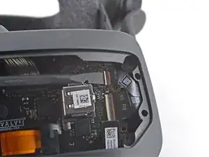
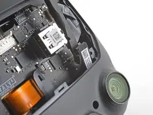
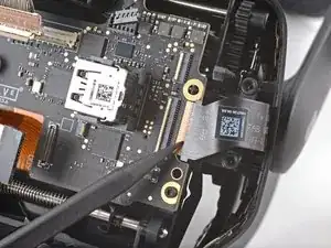
    • Use a spudger to unlock the ZIF connector at the top-right corner of the motherboard.

    • Disconnect the FPC ribbon cable.

  17. jH2IyWUVmoEJpOjC
    jH2IyWUVmoEJpOjC
    sLdoecCJxDYjQotq
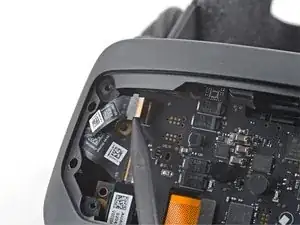
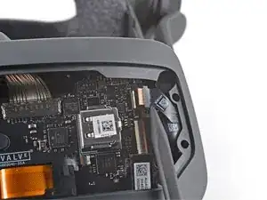
    • Use the flat end of a spudger to disconnect the press connector from the bottom-left corner of the motherboard.

    • To re-attach press connectors like this one, carefully align and press down on one side until it clicks into place, then repeat on the other side. Do not press down on the middle. If the connector is misaligned, the pins can bend, causing permanent damage.

  18. YXiLknBH4VCDnUI1
    YXiLknBH4VCDnUI1
    A6ZPpANoYgpBi3tX
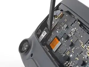
    • Use the flat end of a spudger to disconnect the press connector from the bottom-right corner of the motherboard.

  19. IXGlNvAICcAtJnMy
    IXGlNvAICcAtJnMy
    lPHsHEnOMGa4s52I
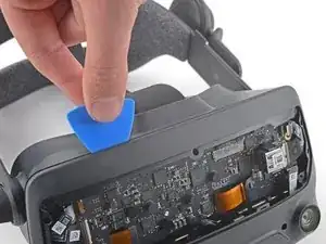
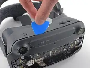
    • Insert an opening pick in between the front fascia and the headset.

    • Slide the opening pick over to separate the front fascia from the headset.

  20. gqEBWUsY5XnKekDl
    gqEBWUsY5XnKekDl
    ZkMvGoWnZAqNDvqI
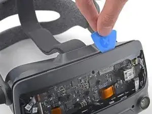
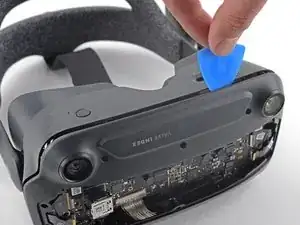
    • Continue sliding the opening pick along the perimeter of the front fascia until all edges are free.

  21. RZCi6PnZwrs1RKPu
    RZCi6PnZwrs1RKPu
    OAqHwP1vehpgWEq6
    • Remove the front fascia.

  22. TCjHR5NYNmCxlC1E
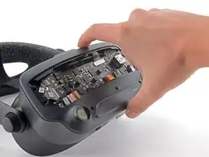
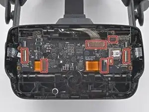
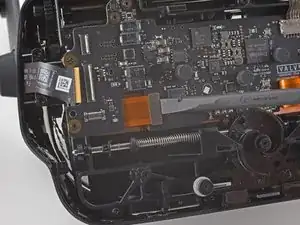
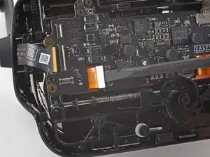
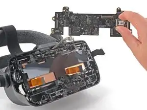
    • Note the seven cables that must be disconnected in the following steps before the motherboard can be removed.

    note that the wheel that adjusts the distance between the eyes goes over the boar. So you will tuck the board under it.

    Michael Hehe -

  23. HQQpZp5QANDclP5I
    HQQpZp5QANDclP5I
    4yCQFuJAjZofGrOo
    LYbGQwjIyjODqh5p
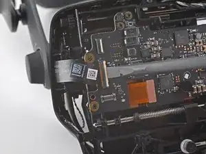
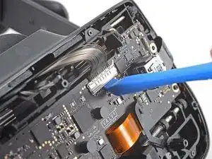
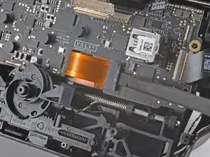
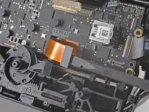
    • Use the flat end of a spudger to unlock the wide ZIF connector on the left side of the motherboard.

    • Disconnect the FPC ribbon cable from the motherboard.

  24. W4S4IqHrXOYwCFBa
    W4S4IqHrXOYwCFBa
    qHsPNGQiifR5DpSJ
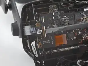
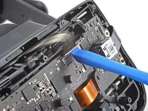
    • Use the flat end of a spudger to disconnect the press connector near the bottom-left edge of the motherboard.

    • During reassembly, be sure this cable is not trapped underneath the motherboard.

  25. gNkeRbLXFjHFZyie
    gNkeRbLXFjHFZyie
    1B3xtjGE3wLrXQ3E
    jJE6TtTAmmNCVpyB
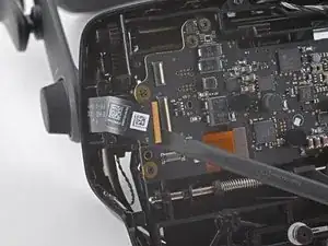
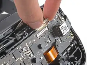
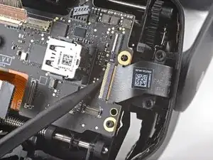
    • Use your finger or an opening tool to unlock the display cable connector at the top of the motherboard.

    • Carefully disconnect the display cable connector.

    this one is pretty difficult, and could use some more explanation (esp since the teardown video of the index skips it completely). you need to lift up on the corner of the cover, and then use the pointy end of the spudger to slowly wiggle the cable UP and out of the connector, a little at a time on each side.

    Owen Smith -

  26. 4UXYQfOJC3IVUOBE
    4UXYQfOJC3IVUOBE
    FIWi3Tdys6UErNqJ
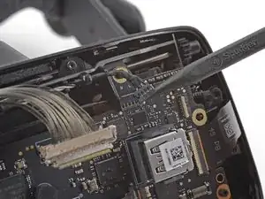
    • Use the pointed end of a spudger to gently disconnect the bundled cable connector from the top-right corner of the motherboard.

    don't push up on the indented plastic

    Jose Zamora -

    This pops out towards you, do not try to push up.

    Storm DPD -

  27. QL2UqWW1CYCdtIIp
    QL2UqWW1CYCdtIIp
    QcTyN5YwO3SeKWQU
    Gaa4RjVFZNGiUoOo
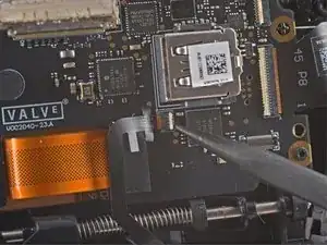
    • Use the pointed end of a spudger to unlock the ZIF connector next to the USB port on the motherboard.

    • Disconnect the FPC cable from the motherboard.

    • During reassembly, make sure this ribbon cable is not trapped under the motherboard.

    Not sure if this is on every headset, but mine had adhesive holding this cable to the motherboard and to the press connector cable. Be very careful peeling these apart, the adhesive is a little strong. Using the guitar-pick looking thing from the fix kit managed to separate them for me, but it might have been sheer luck lol.

    Owen Smith -

  28. oXd3I5plhXSKkDfJ
    oXd3I5plhXSKkDfJ
    oICKoYOMEmqVOXRT
    • Use the flat end of a spudger to disconnect the press connector below the USB port on the motherboard.

    • During reassembly, make sure this cable is not trapped under the motherboard.

  29. WGpqUYMeUubjUo11
    WGpqUYMeUubjUo11
    HywiclnUqKGIJ6wk
    aTjmMd4WXnSGAZ5o
    • Use a spudger to unlock the wide ZIF connector near the right edge of the motherboard.

    • Disconnect the FPC ribbon cable from the motherboard.

  30. QmpYEpvEZLR2iOHP
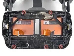
    • Use a T5 Torx screwdriver to remove the five 6.0 mm screws securing the motherboard to the headset.

    These are a set of 5 coarse threaded screws.

    Patrick Hartge -

  31. 1VowAHqkQjSodGRG
    1VowAHqkQjSodGRG
    ouJidliMDFMjJHbk
    • Grab the motherboard by the USB port and carefully remove it from the headset.

    • During reassembly, be very careful not to trap any of the previously disconnected cables under the motherboard.

    During reassembly be sure to align the ipd slider with the gap on the back of the right eye tube. The ipd adjustment slider is located on the top left of the motherboard and is very easy to miss.

    Failing to align that the motherboard and the eyetube will result in resistance while adjusting the ipd, as well as an incorrect ipd being used in steamVR (which doesn't feel too great).

    Aux -

  32. 3oC4VOQmIMRXGsDk
    3oC4VOQmIMRXGsDk
    BKG1GKQLTnIK4BNw
    • Lift the motherboard shield off of the two cross-shaped alignment pegs.

  33. bfOSY6CEebF3AY3B
    bfOSY6CEebF3AY3B
    vGHv4yGYliVSDKrb
    • Use your tweezers to remove the rubber boot covering the IPD adjustment screw.

    On reassembly, the best method for getting this back on is to get one end on and pulling until it's about half on. Then begin pulling with tweezers and spinning at the same time.

    Patrick Hartge -

    if you're struggling to get this back on, I'd recommend prying at the underside (specifically at the part with the little dent on it) with your flathead screwdriver bit until it splits, then pulling it on and over, using your screwdriver to fold the two halves of the rubber over the screw.

    Owen Smith -

  34. egUbvymn2kkSkRdM
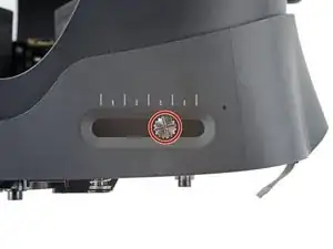
    • Use a 2.5 mm (3/32 in) flathead screwdriver to remove the 6.5 mm IPD screw from the headset.

  35. XRxoeDbgYXxJOEEF
    • Use a T5 Torx screwdriver to remove the five 4.5 mm screws securing the midframe.

    These are fine threaded screws, in case you get your screws mixed up. They are also defined by the only set of 5 with blue locktite on them.

    Patrick Hartge -

  36. IVCdWZNvKoHtDHb6
    IVCdWZNvKoHtDHb6
    qusNLrdWFxMpFpda
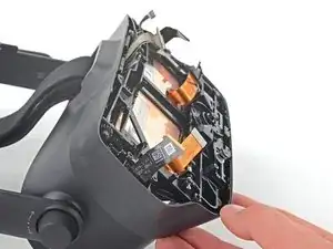
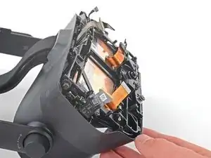
    • With the midframe loose, slide the case towards the back of the headset to expose the eye tube rails.

  37. NtnfH4aq3AtoWrxl
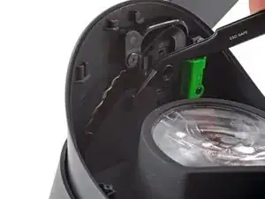
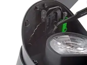
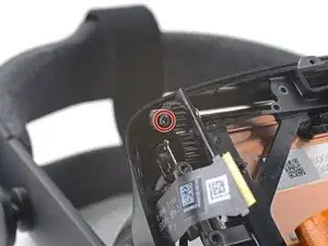
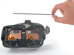
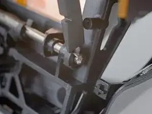
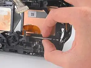
    • Use a T5 Torx screwdriver to remove the 4.4 mm screw securing the left end gear to the eye tube rail.

    • If the screw is not accessible, turn the eye relief knob to rotate the gear until it faces outward.

  38. Rb1fEEOsFPr5mbEI
    • Remove the left end gear from the eye tube rail.

    Be careful, there are retainers and plastic bushings on the outer sides of the rail, just inside of the midframe. I removed these with tweezers as I slid out the rail. To reinstall, I had to feed the retainer through the little hole in the front of the midframe and work it into place with the tweezers. I got the final positioning with the pointy end of a spudger. You can see one of the retainers in this picture, just to the right of the inside of the midframe where the rail is sticking through. The hole to feed it through is just below it, where the last bend of the retainer is sticking out.

    Ulric Dettweiler -

    This guide says "Remove the left end" but I suggest deciding based on the side you want to actually change.
    I left the both top and bottom bars in place and just pulled them out as much as needed to free the eyetube on the side I wanted to change. it makes your life way easier!

    Pouya -

  39. L21THYK61Zi4MQ4x
    L21THYK61Zi4MQ4x
    lJeV2U4QFa6RuSiR
    YVxrsOG6m2MqWnHa
    • Grab the gear on the opposite side and slide the eye tube rail out of the headset.

    • When removing the upper eye tube rail, two plastic bushing will fall out and two metal springs may fall out. Keep track of these parts.

    • During reassembly, slide the bushings back on to the eye tube rail and use a pair of tweezers to align the springs to their original positions.

    I had two small black pieces that look like they belong on the eye rail pop off on this step. https://imgur.com/a/tZ1mxPf Anyone have any idea where they go back on during re-assembly?

    Tyler MacInnis -

    I had this problem too. If you look at the below disassembly picture you can see that these are bushings on the inner side of the gear axel. This is extremely easy to miss. They face opposite sides and are on either side of the axel, there is also a spring on the inside of these that is completely neglected in this guide.

    These bushings are used to ensure that the FOV adjustment axel gears remain flush.

    https://imgur.com/a/uP7mVGt

    Xayrga -

    Wish i had read the comments here. Both the little metal bar and plastic piece went flying on both sides when I removed the rod. Took me a good hour to find one that fell. Honestly the hardest part of reassembling this for me was getting that little piece back how it's supposed to be on both sides.

    Gray Corgi -

    Did you have just one metal bar or two? Could have sworn two popped out but now I can only find one. Did you happen to snag a picture?

    Astrid Wood -

    To answer my own question. Yes there is a set of bushing and spring on each side. The spring here is a bent piece of metal, with some bends in it. The side with the larger bend goes into a small hole at the bottom and is used for retention. If you thread the top through the hole and kinda get it in there straight you will see how it lines up. This is a pretty big step for iFixit to miss. It is a pain to get in so if you are reading this beforehand use some tape or tac to stick the side coming through the hole in the plastic frame down. Much easier to get it all in that way.

    Astrid Wood -

    Any easy way of getting those springs back in cuz &&^& me I can't get em

    Death Venom -

  40. IbgjEZTWZ3FVaxZU
    IbgjEZTWZ3FVaxZU
    ePQYwABQuPetWhDk
    eBnt3Cr6Bv4PvBKn
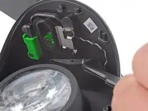
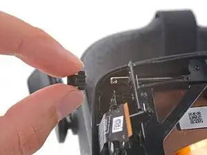
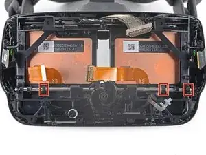
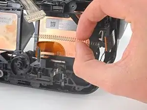
    • Use a spudger or your fingers to remove three of the four clips from the lower eye tube rail.

    • Hold the clips steady with one finger to prevent them from ejecting.

    • To reinstall these clips, place the open end on the groove in the rail and press them into place.

    • Two of the clips require holding the spring back to install them.

  41. gxqQiyViXkrQ2pPB
    gxqQiyViXkrQ2pPB
    EUfI5SFBRqE1rA3T
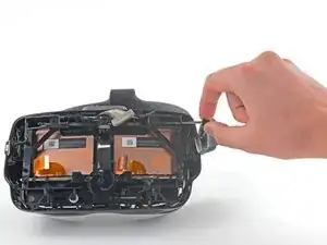
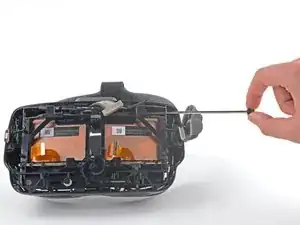
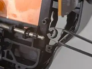
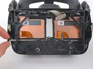
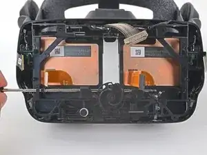
    • Hold each spring with one hand to prevent them from ejecting as you slide the lower eye tube rail out.

    • During reassembly, slide the springs on to the rail and carefully "walk" them back with your fingers until they are entirely on the rail.

    I ran into a problem with reassembly somewhere at this point--two very small black parts seem to have fallen out and now the headset's eyepieces won't return to the middle, only stay where they are if moved with the IPD slider.

    Foxhound -

  42. LZMwNJypWtPDRTGa
    LZMwNJypWtPDRTGa
    GUFiKXPEaglKgmEb
    EeJ5a1PGOjQPVHDS
    • Remove the lower eye tube rail.

    • The eye tubes are now loose and can fall out.

    If you're like me and had the swirly gear piece thing in the middle fall out, make sure you put it back in correctly or your IPD adjustment will be wrong. You can use the picture in the guide as reference for the position of that piece vs the position of the IPD slider. Move the slider at the bottom left screw with white washer thing to the same position as in the guide, and drop the swirly gear in the exact position as shown in this guide.

    Alternatively, you can push the IPD mechanism into the lowest IPD (closest together) setting and set the swirly gear thing in the position where both of the little half circle "notches" in it are perfectly horizontal / at the same level on each side.

    Gray Corgi -

  43. Ik1qXwkHfUTLSxQu
    Ik1qXwkHfUTLSxQu
    YrTWJKAQnrVHWEV2
    • Remove the eye tube(s).

    • The eye tubes are a tight fit and can be tricky to remove and install. Try different orientations as you work them in or out; do not force them.

    The reconstruction steps should be included as well...

    Phillip Hochman -

    Installation is opposite of removal

    Jayce Feldmann -

    Wasn't exactly opposite, those springs did not want to go back in!

    Fizz -

    I can't seem to lift the eye tube out, there is this plastic part in the front that blocks it (they are loose but there is no position in which they can be removed):

    https://files.catbox.moe/it930u.jpg

    https://files.catbox.moe/lqq7lk.jpg

    Owen Smith -

    I also have that plastic part. it is glued to the inner plastic frame. So I left it alone just folded it out of the way so that eyetube could be pulled out ( bottom side first)

    Pouya -

    I have that part too. I was able to get the eyepieces out by tilting them back, and then flexing the top of the index to let them slide underneath it. Make sure that your eye relief adjustment is as far out and thus as loose as you can make it.

    Aric TenEyck -

Conclusion

Compare your new replacement part to the original part—you may need to transfer remaining components or remove adhesive backings from the new part before installing.

To reassemble your device, follow the above steps in reverse order.

Take your e-waste to an R2 or e-Stewards certified recycler.

Repair didn’t go as planned? Try some basic troubleshooting, or ask our Valve Index Answers community for help.

Sam Omiotek

Member since: 25/02/19

62518 Reputation

12 comments

I gained two extra small pieces not mentioned, I think when removing the top rail, they just dropped out into the housing. Looks like they go next to the eye tubes and are not included with the replacement so make sure you don't lose them!

https://imgur.com/a/AW4dHOW

Fizz -

I believe those are suppose to add tension to the top rail. I lost mine but it should be for a small metal spring tensioner (I think).

Gabe -

Great guide. Thanks so much!

David S -

Hey, you guys forgot to mention anything about 2small pieces of bent metal no thicker then a staple that looks pretty important. Might want to include every piece that may be affected when assembling/disassembling the headset, Especially in the later stages.

Jesse the Dragon (Dragon) -

wtf are these??? I also had them fall out and don't know what they are!

Patrick Hartge -

If for some reason you broke the audio connector on step 26, the part number you are looking for is Molex 781710005 and the plug is 781720005.

ikindafixedit -

My IPD adjustment is way out of whack now after a left lens replacement. It's reading much higher numbers than actual and the lowest possible setting reads at 63 or so. Anyone else have their IPD adjustment go off? Any ideas on how to fix it?

Jeremy P -

For reference I figured this out with help from a comment at the motherboard stage. There is a tiny slider at the top left of the motherboard that fits into a slot on the rear of the RIGHT eye tube (the left eye tube when looking from the motherboard side). When that slide is properly in its slot the digital IPD lines up with the physical IPD correctly. I had missed it when doing a left eye tube replacement because I hadn't focused on the other side.

Jeremy P -

After replacement my windows cannot recognize the headset. In device manager it says "unknown usb device (device descriptor request failed)"

Anyone know how to fix this? I have tried a lot of methods found online, tried replugging, reinstalling...

lance2499 -

Is there a way to test which of the eye tubes is faulty?

Mike -

wear it. see what eye tube is faulty. play a game.

Paul Treagan -

Did it and thanks to this guide the Index is working again.

For everyone searching the web: My symptoms were vertical white lines in my left eye. Got the new eye tube from iFixit and everything is working now!

The Guide needs two updates though.

Step 39 needs to show the black pieces and springs for reassembly as this was very hard. (I think one of the parts is missing in thge pictures of the guide ;-) )

And There seems do be a newer version of the headset that has a plastic plate over the bottom parts of the tubes that prevent them from being extracted. This part is missing in this guide.

BIG THX @samomio for the guide and iFixit for having the part!

Robert -