Introduction
Occasionally the dryer may become too loud as a result of a faulty motor. This guide details the steps taken to replace the motor. Disassembly of the device requires a special bit for removal of tamper-proof screws.
-
-
To change the motor, start by removing the metal casing.
-
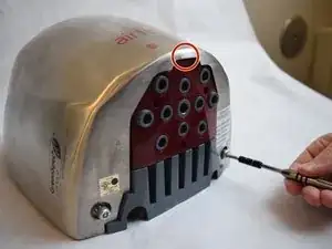
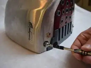
Using the special bit, remove the large screws at the bottom of the casing.
-
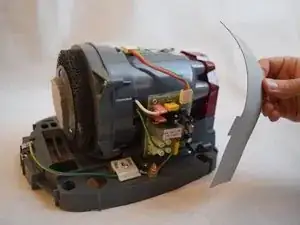
To remove the case, lift the indicated spot with your hands.
-
-
-
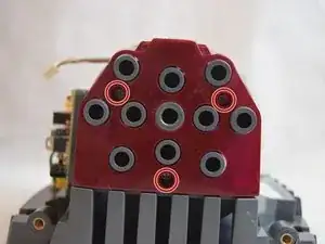
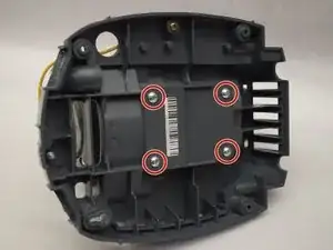
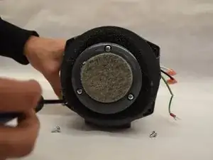
Remove the three 1/2" Ph1 screws at the bottom of the red fan cap.
-
Turn over the device.
-
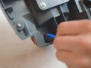
Push the red tabs on the back of the unit with medium to heavy pressure, using a small prier.
-
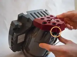
Carefully remove the cap, to prevent damage to the sensor.
-
-
-
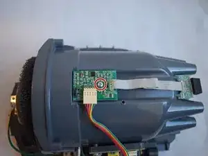
Remove both 3/8" Ph2 screws attached to the grey belt at the top and bottom.
-
Lift the grey belt away. This gives access to the server board.
-
-
-
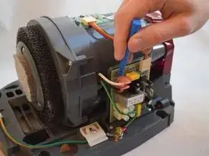
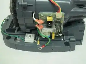
Use a plastic opening tool to remove the two pink capped wires in the upper left corner of the server board.
-
-
-
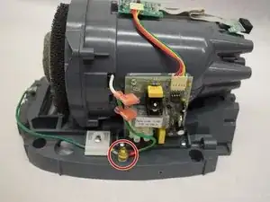
Remove the brass nut from its bolt using a 10mm wrench.
-
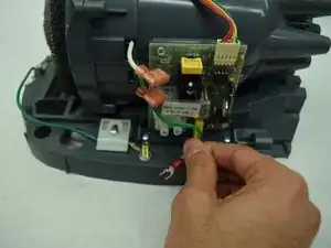
Once the nut is free, disconnect the green wire.
-
-
-
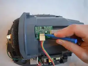
Remove the rainbow ribbon cable using a plastic opening tool.
-
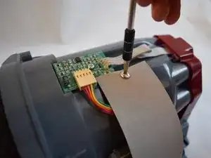
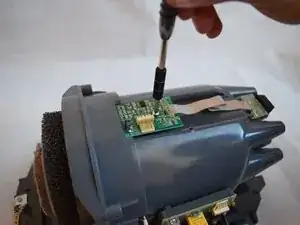
Remove the 1/2" Ph1 screw from the center of the circuit board.
-
-
-
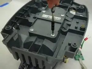
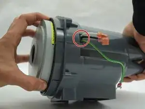
Remove the four 3/4" Ph2 screws from the back of the device body.
-
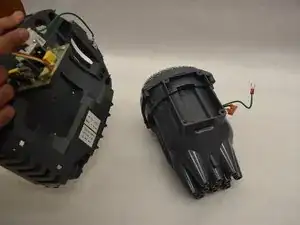
Separate the motor housing from the device body.
-
-
-
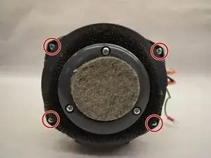
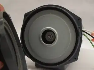
Remove the four 1/2" Ph2 screws from the filter.
-
Pull the filter plate away to reveal the motor.
-
-
-
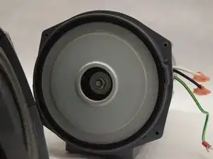
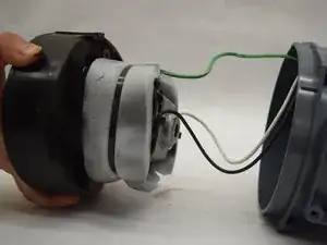
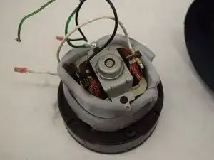
Pull the motor out of the housing.
-
Be sure to feed the wires through the slot as you pull the motor out.
-
To reassemble your device, follow these instructions in reverse order.