
Introduction
How to hook up 6 pin( pinout-given ) inverter direct to PSU and have a backlight without motherboard
-
-
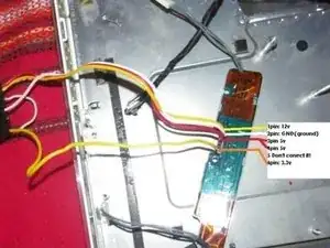
That is the G5 17" A1058 Inverter pinout with 6 pins. I took it down myself from the board with a multimeter and the ICs Datasheets.
-
12v is the main soruse
-
GND is ground
-
5V supplyes Op amp on the sheme that gives the niveau of backlight, It cant be lower than 5v so actualy it dosn't regulate the dimm of the light.
-
5v The second line Gives the Enable signal ot the inverter
-
Dont connect. It goes to a gate of two mos transistors k72 SMD and is protected trought a diod directly after the pin. It should turn on these Transistors but when I give it supply, the backlight goes off and doesn't turn on back again when i remove the supply (I tried 5v) Fixed it with reset of the PSU.
-
3.3 v. Again goes on set of MOS transistors. Their gates should be capable of taking up to 5-10 volts. But I decided to play it safe. It makes the backlight brighter( that is the light dimmer). Whitout it the backlight works but isnt brighter as it should.
-
To reassemble your device, follow these instructions in reverse order.
One comment
You connect the 5v without the GND? The GND is just connected to 12v??? I just see 1 cable making the 5v. HELP!