Introduction
I am going to show you how to take apart this Coby alarm clock with a digital photo frame.
-
-
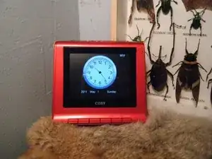
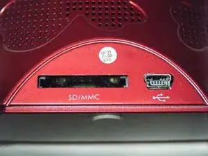
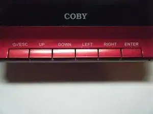
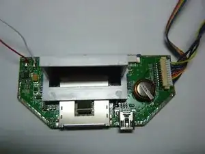
Here are the specs. This clock features a computer connection port, an SD card slot for the photo viewer, and buttons, including a snooze button. It also has an MP3 player, but no headphone jack. How Strange. It also does not have internal memory, which is why there in an SD card slot. But, The real nice thing about it is the fact that it includes a color LCD display!
-
-
-
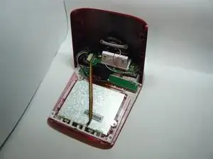
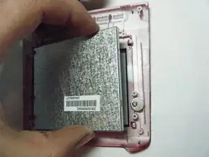
After two outer case screws are removed, The two halves of the case can be easily snapped apart.
-
-
-
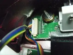
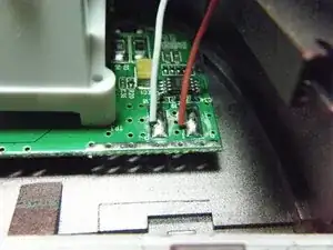
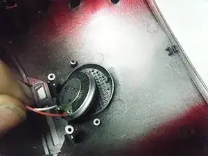
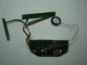
Too bad the speaker and control wires are soldered to the logic board. The speaker is held on by two solder pads. The button control cable connecter may look like it's detachable, but it wouldn't come out. It looks like They get to spend the rest of their lives chained together. But what about the LCD? Is that replaceable?
-
-
-
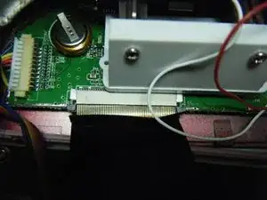
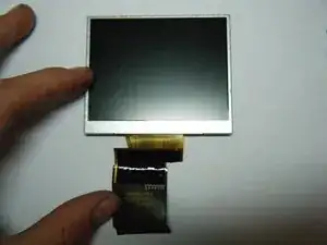
Yes! the LCD is not soldered on the logic board. It is held in by a ribbon cable connecter. It can easily be removed.
-
What a pain it would be to have it soldered in the logic board.
-
-
-
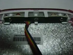
After taking out two screws, the inner snooze button comes out.
-
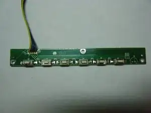
They are 2 buttons on this board, along with a few capacitors and resistors.
-
-
-
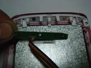
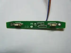
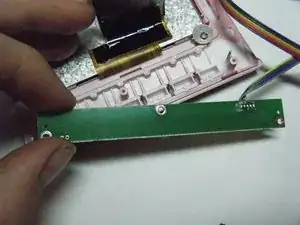
After removing the three screws holding down the control pad board, It can be easily lifted out.
-
On the other side of the board, just buttons.
-
-
-
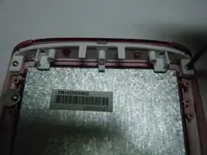
they are 2 metal clamps held on by each one screw, holding the LCD down. Make the screw a little loose and turn each clamp around.
-
-
-
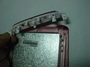
But before the LCD can be removed, the outer snooze button assembly has to come out. It is held on by two screws.
-
-
-
The LCD can finely be removed!
-
The screen quality and size is not too bad for the price I paid for it.
-
-
-
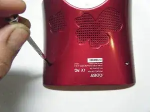
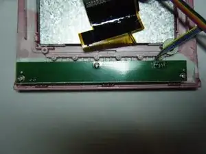
These two plastic pieces hold down the speaker and logic board to the rear case. the screws holding them down must be removed.
-
-
-
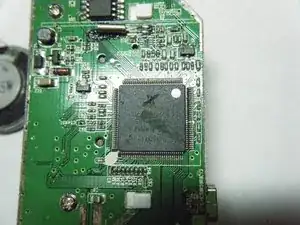
The chip. The brain. The micro controller. My favorite part.
-
Their is only one chip on this logic board. No wonder their is no internal memory. This is just the CPU.
-
-
-
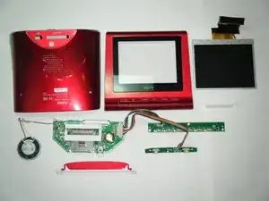
Done!
-
I would give this a score of 7 out of 10. I am deducting 3 because some parts were soldered to the the logic board, making replacement difficult.
-
The good side is that the screen was replicable, and the fact that the whole thing was held together by screws, and not glue.
-


One comment
2011 tear down, but here in 2016 December I actually found that useful. Thanks for taking the time to share.
misc -