Introduction

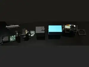
This guide show you how to take a first generation Lytro camera completely apart, all without causing any damage. I've seen some other guides, but none of them explain how to reattach the camera lens cable. If you take the camera apart using the steps provided in this guide, you won't even have to ask how to reattach the cable. I believe this is the proper disassembly (i.e. the reverse of how it would have been assembled at the factory.)

  1. S5HtLyOXs2NIFYgj
    S5HtLyOXs2NIFYgj
    N5DWKadSJeU43LaA
    4jxiQFLoZT1wuTuM
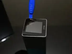
    • Insert a plastic spudger between the rubber trim and the edge of the screen.

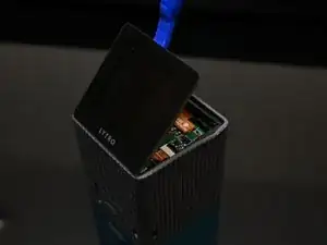
    • Gently pry at the edges of the screen until it begins to pop out. It is held in with a rubbery adhesive.

    • Be careful not to damage the ribbon cables when levering the screen out. The cables are on the bottom side (power button / Lytro text side) of the camera.

  2. qtSh5YXMwHxBF5F1
    qtSh5YXMwHxBF5F1
    YJOUKqIkugPybTjb
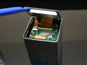
    • Carefully disconnect the ribbon cables from the screen.

    • The connectors have hinged latches which can be opened with tweezers or a small flat blade screwdriver.

  3. UVJSXYu3qSJ4CIoK
    UVJSXYu3qSJ4CIoK
    RK3QyodcChLmNxLG
    • Remove the four screws which hold this board in.

  4. EkGaH1lLRJpld3pU
    EkGaH1lLRJpld3pU
    KhwvHlQnUeIXKdfK
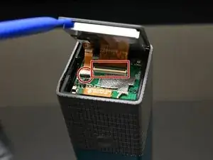
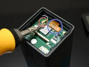
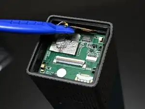
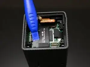
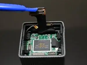
    • Remove the antenna cable. This is covered with conductive tape which you will need to partially peel away.

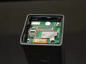
    • Remove the zoom control ribbon cable. This one is just snapped into a connector on the board. Gentle prying will remove it.
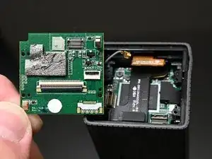
  5. eFDVLvEs1R1iI6US
    eFDVLvEs1R1iI6US
    wxtGboCMRqwtQK1R
    • Pry the board out.

    • Note that this may require a spudger or a small flat tip screwdriver due to the board-to-board interconnects on the back.

  6. wZBERTiuIWkNMY1q
    wZBERTiuIWkNMY1q
    LFIPRICqhmOyOkBL
    • Disconnect the ribbon cable for the lens/sensor assembly.

    • This ribbon cable is snapped into a connector on the board as well. Just apply a little leverage and it should come loose.

  7. OGcrq3VaSrJ2HXUg
    OGcrq3VaSrJ2HXUg
    aMK62Q32ycUHPgBi
    x5rQ21SAKXtJptMZ
    • Flip the camera upside down. We need to work on the lens side now.

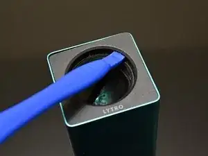
    • Insert a spudger between the lens and the plastic trim on the front of the camera.

    • This is why we're specifically using a plastic spudger. A metal spudger would scratch the lens badly.

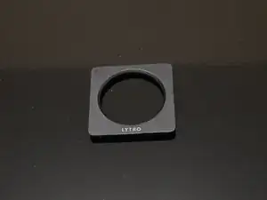
    • Pry up gently to break the adhesive and remove the face plate.

  8. xjYxeQ6htmA2Ile3
    xjYxeQ6htmA2Ile3
    vyOaZFKvBxhBnFsK
    ZHZYrOaOAgEOiJya
    • Remove the four screws that hold the lens assembly on.

    • Note that these screws are extremely long and fairly unique looking. They're pretty hard to lose, but don't bend them. You'd probably have a hard time finding replacements.

  9. uHDHqanJMlEo6EJr
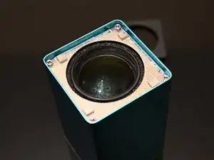
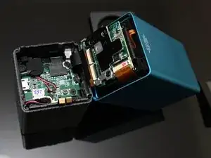
    • You can now open the camera by breaking it in half at the seam between the rubberized grip and the anodized lens housing.

    • Note that the ribbon cable for the lens is on the top side of the camera. Treat the top as if it were a hinge and open the camera from the bottom (power button/charge port) side. You should have plenty of slack from disconnecting the other end, but be careful.

  10. l6WHHBUuhP1PtkxB
    l6WHHBUuhP1PtkxB
    VQCAE4tjlXXZrIbQ
    • Disconnect the battery.

    • The battery wires are tucked behind the connector from the factory, so you may need to push those aside to gain enough room to pull the connector out.

  11. pdHyUetRmRhPnSIe
    • Disconnect the ribbon cable in the opposite corner from the battery.

    • There is a double-sided sticky pad under the cable, so you may have to use some force to remove it from the board. The connector itself is just snapped in like the last couple of ribbon cables we disconnected.

  12. 4DEY1EdQW1w3GHoa
    4DEY1EdQW1w3GHoa
    sUhu2mJMKsmOHFDa
    tYFNDOQgkTpJVsei
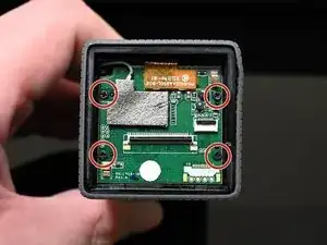
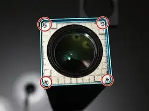
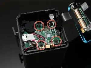
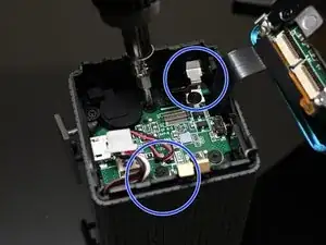
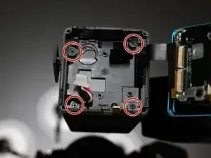
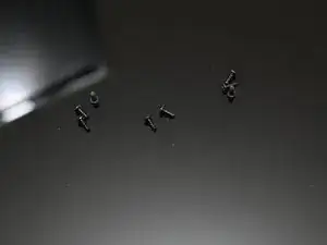
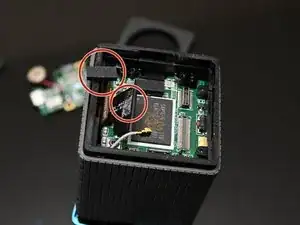
    • Remove the four screws that hold this board in.

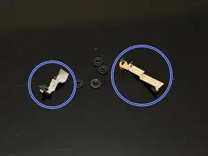
    • Pay special attention to the two screws which retain metal... things. One of these is definitely required for proper grounding/RF compliance (not sure about the other). Do not lose these.

  13. oMIRskudEoTFVl3Y
    oMIRskudEoTFVl3Y
    TWykKkRJFvKJch4f
    sWPdrKMn11lUFxGB
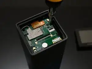
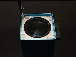
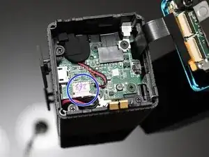
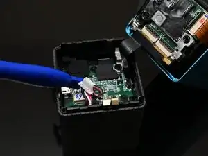
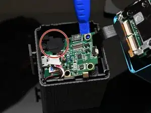
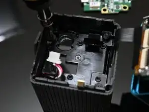
    • Pry the board up gently.

    • Do not remove it completely yet! The speaker wires are thin and delicate!

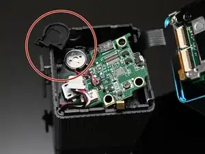
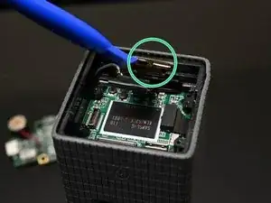
    • Remove the rubber cap from the speaker.

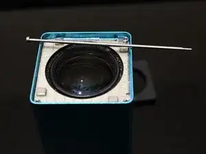
    • After removing the speaker cap, the speaker is just held in with adhesive and can be gently pried up.

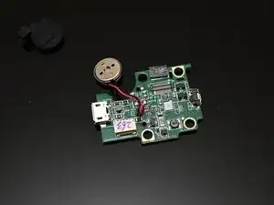
    • Once the speaker is free, you can safely remove the board.

  14. UCZqcO5wZTAQsYQ2
    UCZqcO5wZTAQsYQ2
    HyMoqcAAjHNdBUjq
    wp3OB3LyMvYf2cHO
    • Remove the four screws which hold the battery/CPU sub-assembly in.

    • Note that these screws are identical to the ones you removed from the interface board earlier. No need to worry about mixing them up.

  15. mS6W3SZ4xrMToLXf
    mS6W3SZ4xrMToLXf
    EPXVmFh4GNDETpkm
    eHs5qoxLnQ6d1TkX
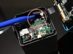
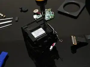
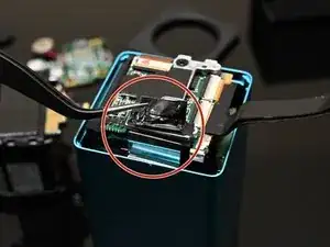
    • Remove the foam pad from the back of the lens/sensor cable.

    • With the foam pad attached, the cable would be too thick to fit through the narrow channel we're about to pull it through.

    • Be careful to watch for how the zoom control ribbon cable and the lens/sensor cable are moving as you push this next sub-assembly out.

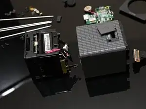
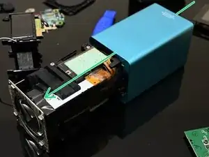
    • Push the battery/CPU sub-assembly out gently from the lens side (i.e. toward the screen side) of the camera.

    • If the assembly does not slide freely (and it probably won't) do not force it. The ribbon cables are delicate and you can tear them. Use twezers if you need to, but carefully guide the cables through the holes in the battery/CPU assembly as you push.

  16. KZ5YpFFYbEb43MDI
    KZ5YpFFYbEb43MDI
    UyMFQmMF62D4uQOg
    fOYLrFmAUwjtqjsF
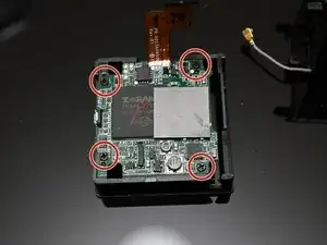
    • After pushing the CPU/Battery assembly out, we need to remove four screws to separate the CPU board from the battery assembly.

    • These screws are on three different sides of the assembly.

  17. MIV3KxPOo4mJMjw3
    MIV3KxPOo4mJMjw3
    EpIGyH4koUYU2LTd
    • The CPU board is held onto its frame with four screws. You may remove these if you need to replace the CPU board.

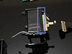
    • The battery is held onto its frame with some adhesive foam. You can cut this foam with a knife to remove it.

    • Be careful not to puncture the battery.

    • I did not perform either of these steps during my teardown, so I do not have photos.

  18. CIOqHWsMPYH1HUrR
    CIOqHWsMPYH1HUrR
    qtvGgoH5PrOLVils
    ngboITxl3DKNBkIQ
    • At this point, the only thing holding the lens assembly in its housing is a single piece of tape. The adhesive is not strong. Lift it with a pair of tweezers or the like.

    • After the tape is lifted, the lens assembly can be pushed out from the back (from the screen side of the camera).

  19. iLfnqa3X22F63TJZ
    • That's a wrap! Reassembly is mostly just the exact same steps, but in reverse.

    • However, there are a couple of things to be aware of when reassembling the camera, so continue reading if you need some tips.

  20. BnFDvtERDwOKRQPC
    BnFDvtERDwOKRQPC
    mYG3QqMlfjs4OHZt
    JOiLJCTXZOQGiM5s
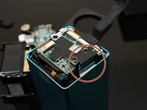
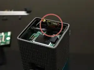
    • The zoom control ribbon cable is tricky to get back in position. It needs to be threaded through a hole in the battery/CPU sub-assembly housing.

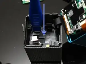
    • Start with the cable on the outside of the housing, then tuck it through the hole pointed to by the red arrow.

    • After tucking it into the hole, the cable should be poking out underneath the plastic support pointed to by the green arrow.

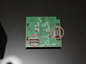
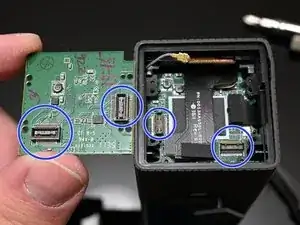
    • Be mindful of the board-to-board interconnects when replacing the interface board. There are plastic pins which help align the board, and the screws should apply enough pressure to snap the connection together, but you may want to make sure that they're together by pressing gently behind the connectors until you hear them click.

Michael Calvin

Member since: 20/02/23

301 Reputation

0 comments