Introduction
This guide explains the teardown of the GPS Garmin Nuvi 200.
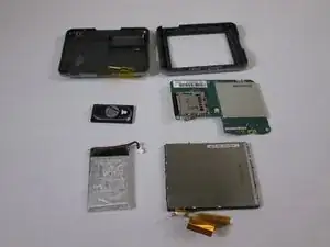
The guide shows the parts of the device, and which of those parts are replaceable. Note that Ifixit also provides repair guides for the battery, LCD screen, speaker, and rear casing.
-
-
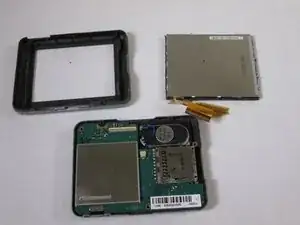
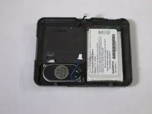
Top left: back casing
-
Top right: front casing
-
Middle left: speaker. Part ($29) and service at portatronics.com
-
Middle right: motherboard
-
Bottom left: battery. Part ($5.20) at amazon.com
-
Bottom right: LCD screen. Assembly kit ($49) at portatronics.com
-
-
-
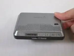
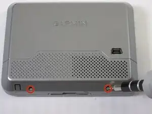
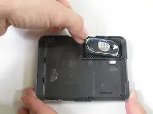
The Serial Number Strip is at the base of the device. Remove it to two expose two T5 Torx screws.
-
Using the T5 Torx screwdriver, remove the two T5 Torx screws.
-
-
-
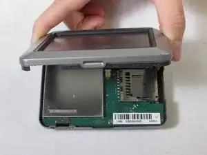
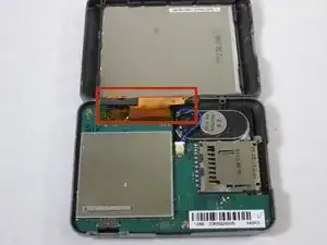
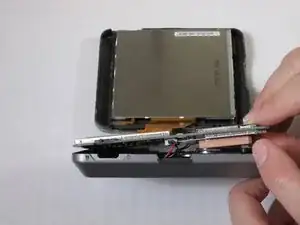
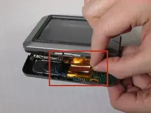
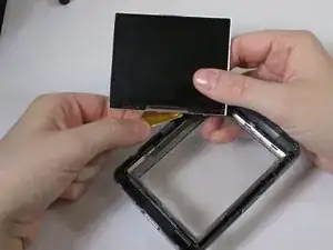
Use care. Do no break apart the strip of orange tape that connects the LCD screen and motherboard (red box in third picture.)
-
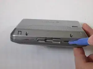
Using the plastic opening tool, only at the bottom of the device, separate the back panel from the front panel.
-
-
-
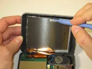
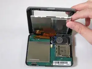
Using the plastic opening tool, push apart the clasps holding the LCD screen in place.
-
Wedge the plastic opening tool between the LCD screen and the metal frame of the device.
-
-
-
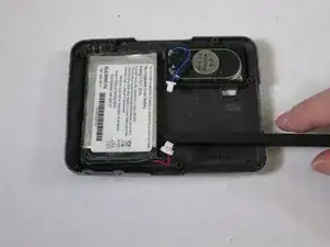
Hold the blue wire from its connector head.
-
Pull the connector head out of the outlet to unplug the speaker.
-
-
-
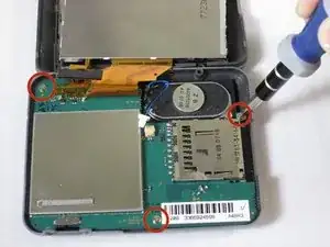
Using the Phillips #PH00 screwdriver remove the three screws that hold the motherboard in place.
-
Use Screwdriver bit #PH00 in IFixIt's Tool Kit to take out the three screws holding the motherboard in place.
-
-
-
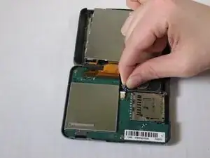
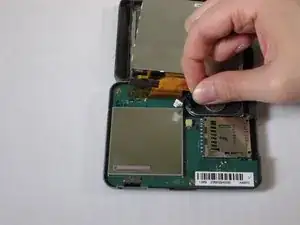
Peel the strip of orange tape from the white attachment bar on the motherboard.
-
This detaches the motherboard and LCD Screen (see second picture for blue box).
-
-
-
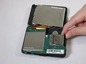
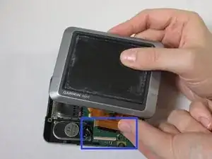
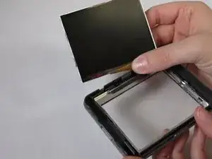
Remove the strip of orange tape from the LCD screen to detach the LCD screen from the front casing.
-
-
-
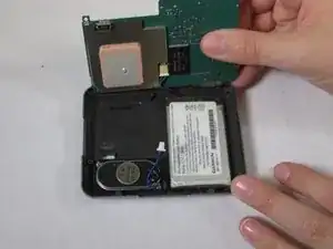
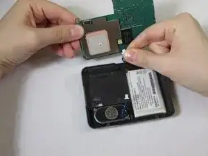
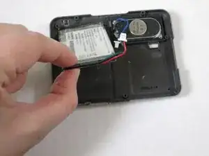
Prop the motherboard up.
-
Hold the red and green wires from the connector head.
-
Pull the connector head out of the outlet to detach the motherboard from the back casing.
-
-
-
Use care. The back casing and battery are glued together. Do not puncture the battery.
-
Push the flat end of the spudger under the battery and separate the battery from the back casing.
-
-
-
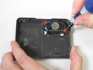
Using the Phillips #000 screwdriver remove the two screws holding the speaker in place.
-
Remove the speaker.
-