Introduction

  1. BLEg1HUybQM6vjwM
    BLEg1HUybQM6vjwM
    D6h4BgTtBygc1L4m
    • one phillips PH1 screw located on the back to remove the battery cover

  2. ipGK6WP4eamxgkS2
    ipGK6WP4eamxgkS2
    bsko4mevNxtvviBe
    oYvA3XjKiZeymcMn
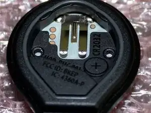
    • Three Tri-point Y0 screws are located under the battery cover

    • Then the Red/White front plate comes out though the front

    I do not believe these Tri-point screws are Y0. Probably Y00. I have yet to confirm it, but Y0 does not fit.

    fltolentino -

    I take that back…a new non-dulled Y0 tri-point bit turns it fine...

    But a Y00 works in a pinch**

    fltolentino -

  3. jfP5C3B54ESwJYkj
    jfP5C3B54ESwJYkj
    YeJ2BJCcqEd2jANZ
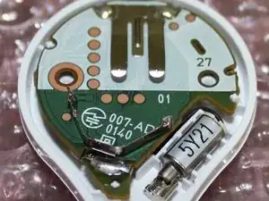
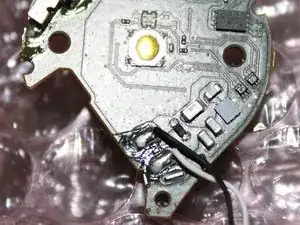
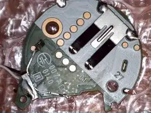
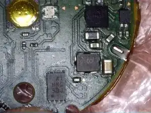
    • the PCB is set on three plastic supports with only the pressure of the back screws to lock it in place

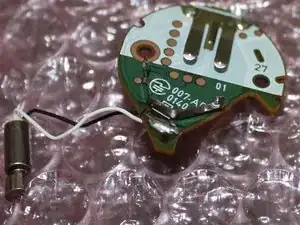
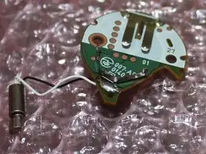
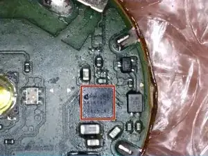
    • the PCB and vibration motor can be lifted out with only the slightest bit of pressure

  4. OIYFdybZrW4Tx6qW
    OIYFdybZrW4Tx6qW
    Lf32lyM42B5FIFe2
    • Function Button located in the center

    • Multi colour led beside button

    can we get a better image of the PCB with less gloss?

    ZexMaxwell -

    So that's why the button is brighter on the top, wish it had a better diffuse so the button was more equally lit.

    jd602 -

    Agreed. I thought mine was busted.

    cynic821 -

  5. mJNtQxOUDVGUZURt
    mJNtQxOUDVGUZURt
    ZVPlRStxnIx5TOVQ
    • Insert wisdom here.

  6. 1Q1eHki6QCHmGowv
    1Q1eHki6QCHmGowv
    l5QxV6nOqICjjCXk
    ZAKU4LK4AsYI3ZHX
    • Dialog Semiconductors Embedded CPU DA14580

  7. er3MURSCaZVVDUqC
    er3MURSCaZVVDUqC
    kItxECFSfJxowmjw
    RlwxNllGHFB13BB4
    • Insert wisdom here.

    there are also test pads under the battery connectors (both of them)

    David Hopkins -

shawn

Member since: 21/03/15

138 Reputation

18 comments

This post needs moar wisdom

corganowade -

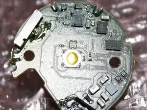
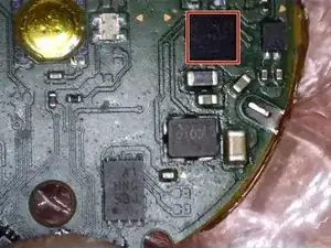
Anybody able to spot a Pedometer?

Luigi Lugmayr -

There is no pedometer. It's just a Bluetooth clicker. Your phone's sensors track all movement.

traviswparker -

What is the

"A1

HNG

SBJ"

chip in "step 6"?

I2C/SPI flash?

And.. what is in "Step 4" the chip? in between the capacitors and that "mostlikely MOSFETs for driving LEDs".

I'm looking at DA14580 modules on ebay:

http://www.ebay.com/sch/i.html?_from=R40...

And I tend to to say "let's try to clone this", the DA14580 has OTA programmable FLASH. :)

Badger -

Last picture is most likely JTAG pogo contact points. For programming and testing. The board seems to be like 3-4+ layer board just based on the pictures. Also can't really tell you what chips those are with that quality of a picture. However the two little chips under the mounting hole on the picture in step 4 looks to be the DC Boost IC to keep constant voltage throughout the batteries life. The chip to the left of those boost converts is most likely the Bluetooth IC (just guessing by the location and the traces around it). Hope this helps :)

Jt Whissel -

Any way you could rig it up to click its self?

Steven -

My thought exactly... is there a way to bridge the button contact via a switch somehow?

Benjamin mitchell -

I know somebody who used a bungee or elastic band with something under it to achieve the same. Works but eats batteries.

Peter van der Kruys -

I placed the PokemonGoPlus into a small box (that does not let light get in), with a light sensor and a SG90 servo.

Then an ESP8266 is running microPython and is moving the servo when light is detected.

I placed an 11 seconds delay between press to avoid false detection with the catch feedback.

It require a bit of tuning to have the right servo angle, also tight fit in the box so that everything stay in place.

Video of this is pinned on my twitter account @DavidGlaude

David “NOeVoting” Glaude -

Automatic catch pokemon:

The top left solder pad of the push-button (seen in figure from step 6) can be connected to the solder pad of the black wire of the motor. The motor can be left disconnected (you can remove the black wire from the motor completely. Recommended. --this will prevent the pogoplus from vibrating). Use a very thin wire to allow the housing to be put back together without your wire getting in the way.

This will make the PoGoPlus click itself.

PokeFixerGuy -

my button isn't making that click sound. what could be the problem?

pogobroke -

I have an Y0 from the old iFixit kit and I can't open the case, that screw is much smaller than an Y0.

Carlos Romero -

Does anybody know where to get replacement screws for the 3 tri-wings?

I stripped out the heads on a couple.

Replacements don’t need to be tri-wing, but knowing where to get a flat head 4mm height, 2.3mm head width screw would be great. Can’t get a good measurement on the threads with calipers. Already tried McMaster-Carr.

Matt Lee -

any luck i lost 2 of them during operations lol

Digerati -

does anyone know the specifications of vibration motor?

Ricardo Victor -

This teardown is in progress – Reload periodically to see the latest changes - 2021

Trevor Falzarano -

My pokemon go plus looks way different on the inside, like 20 X circuit board components. newer version??

Andrew Jenkins -