Introduction
-
-
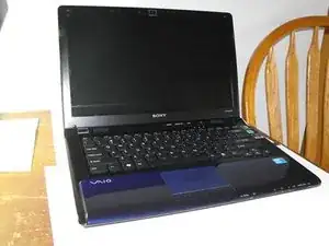
In this guide I'll be doing a full disassembly of a Sony VAIO PCG-61411L laptop. My hope is that you will find some helpful information here and possibly save some money! lets get started!
-
-
-
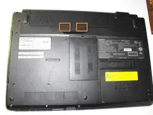
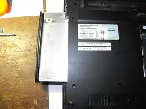
First unlock the battery with the sliding locks (marked with orange indicators), and lift battery up and out.
-
-
-
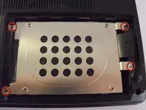
Next loosen the hard drive cover screws as shown (marked with red indicators picture 1) And remove the hard drive bay cover.
-
Remove screws from indicated areas (picture 2).
-
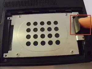
Use the tab (indicated in picture 3) to pull the hard drive to the side and lift it free.
-
-
-
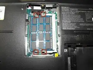
Loosen the screw marked (indicated in the red circle) and pull the RAM bay cover free. (the cover has plastic tabs on the sides and may take a few tries to free it.)
-
push the metal tabs on either side of the RAM chips, making them lean up slightly, and pull both chips free
-
-
-
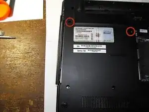
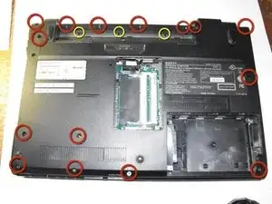
Remove the 15 screws indicated by red circles setting them aside in their own container
-
Remove the 3 screws indicated by yellow circles setting them aside in their own container as well
-
Pull up on tab in the RAM bay as indicated. (the black pull tab may detach, don't worry it will not affect performance)
-
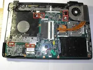
Gently begin to pull the bottom casing free
-


2 comments
I would have to say a partial disassembly, unless I'm missing pages somewhere?
Colm -
As a matter of fact there are 20 (not 15) small black screws (in addition to the 3 silver ones) that hold down the bottom casing. Also, I could not pull the tab in the RAM bay, but was able to rotate the bottom casing around that cable to access the fan, which needed cleaning.
xjekeli -