Cap C5 - (680uF 10V radial) - replaced with 20V equiv.
Questi sono alcuni strumenti di uso comune usati per lavorare su questo dispositivo. Potrebbe non essere necessario ogni strumento per ogni procedura.
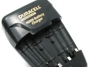
In my case, the charger just stopped working one day. I cannot recall the status of the LED light on the unit.
First, I suggest experimenting with the batteries you have, to verify if the charger is the problem or if it's the batteries (or their charge state). Sometimes, if the charger mistakenly detects that one of the batteries (or its pair in the slot on the opposite side) is already charged enough, it will not start the charging process.
To test this, try inserting those batteries into a different, (dumb) charger which does not test every battery before starting the charging process. Sometimes such batteries will even charge in a smart charger, which does test the batteries, but that charges at a slower rate. Before charging batteries in any charger, ALWAYS ensure compatibility with the charger, or you could risk overheating, or even explosion.
Another thing to try before disassembly is to deplete the batteries a little, by putting them in a flashlight, music player or similar until they have run down (but preferably are not dead) . If the the more depleted batteries charge in this charger, then the charger is likely working as designed. In my case, this didn't work. In such cases, the charger may be damaged. On to the next step...
I needed to desolder a capacitor and replace it with a new one. So you'll need soldering skills, or you'll need to know someone with soldering skills to do this repair.
First, unscrew the four screws on the back of the charger. While the screws are unusual, the correct size slot screwdriver will remove them. A driver too small will strip them.
Capacitor C5, on the beige side of the circuit board, seemed to be bulging a little. On my board, it was a black 680uF 10V radial cap. It can be found just to the left of the yellow transformer. If you replace the capacitor, make sure you insert the new one using the correct polarity. The negative lead (where the white strip on the cap is) inserts through the area of the board that has diagonal lines through it.
On the other side of the PCB, the two solder joints to the right and left of resistors R28 and R28 seemed to have some burn residue on them. I cleaned that residue with with 99% isopropyl alcohol, just in case.
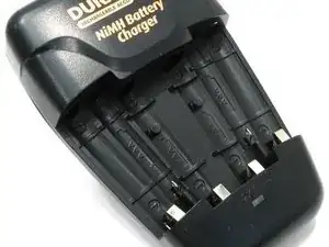
When reassembling the charger, make sure that you first insert the metal contacts which touch the batteries through the front half of the plastic case. Start with the bottom contacts, or you can damage the charger. After the bottom contacts are in, lean the top of the case front forward the front cover and slowly snap it in place. If you use a slightly larger capacitor replacement, like I did, make sure to push the plastic piece inside the case around the capacitor, and that there is enough clearance for case halves to meet without putting pressure on the cap. Also ensure that the metal contacts which charge the smaller, AAA batteries extrude all the way through the front half the case. The first time I reassembled the case, one didn't go through properly, and the charger didn't work.
Insert and tighten the four screws again, and you should have a working charger. Test this by putting in batteries and checking the LED light. Solid red means the batteries are charging. Green means the batteries are finished charging. Flashing red means they are not charging, and there is a problem.