Introduzione
This guide gives step by step instructions on how to access the internals of the number pad on your AT&T CL4940 Corded Answering System. From opening up the device, to removing the motherboard and number pad board, this guide will help you fix your number pad or sticky key problems. Be sure to follow all of the steps in order and pay attention to special notes throughout the guide.
Strumenti
-
-
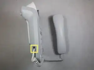
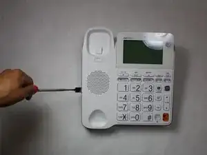
Remove the phone line from the back cover of the device.
-
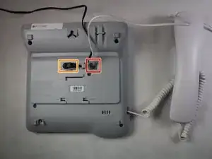
Remove the power cord from the side of the device.
-
Remove the phone cable from the side of the device.
-
-
-
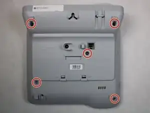
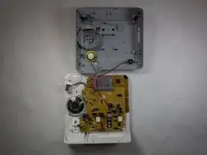
Remove the five 4mm X 10mm screws from the back cover of the device using a Phillips #1 screwdriver.
-
-
-
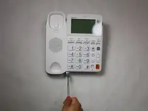
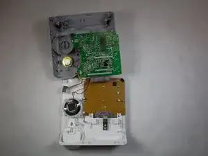
Using a metal spudger, pry the white, plastic cover from the gray, plastic bottom. Start from below the keypad and work your way evenly around the device.
-
-
-
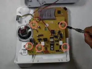
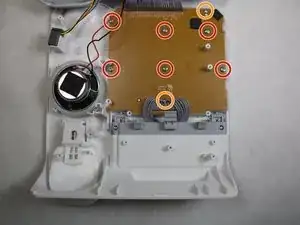
Remove the five 5mm X 5mm screws located on the yellow side of the motherboard using a Phillips #1 screwdriver.
-
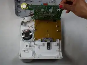
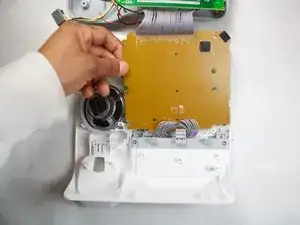
Set the motherboard out of the way.
-
-
-
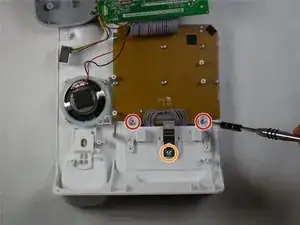
Remove the two 5mm X 8mm large number pad screws using a Phillips #1 screwdriver.
-
Remove the 5mm X 6mm latch screw using the same screwdriver.
-
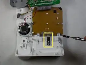
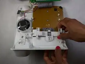
Remove the small, metal latch.
-
Remove the plastic plate previously secured by the screws and latch.
-
-
-
Remove the remaining six 5mm X 8mm large number pad screws using a Phillips #1 screwdriver.
-
Remove the two 3mm X 6mm small number pad screws using the same screwdriver.
-
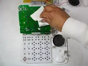
Grab the edge of the number pad board and peel it away from the screw posts.
-
Using a clean towel or cloth, move the number pad board away from the keys that lie below.
-
Set the number pad board out of the way for further disassembly.
-
-
-
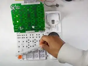
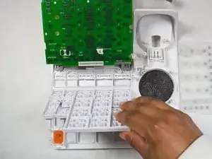
Peel away the white, rubber mat and set it aside for cleaning.
-
Remove the main key pad and any remaining keys. Remember where each key is located for reassembly.
-
Clean the rubber mat with a damp paper towel to remove any dust or foreign substances.
-
Replace any broken or cracked keys.
-
To reassemble your device, follow these instructions in reverse order.