Introduzione
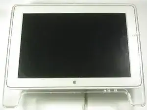
If the display on your Apple Cinema Display M8149 isn’t turning on, is pixelated, or is cracked, use this guide to replace the LCD screen.
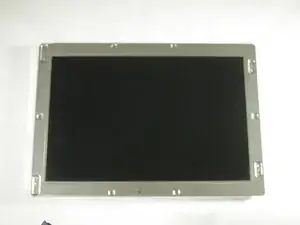
The LCD (liquid crystal display) screen is for displaying computer-generated images. Liquid crystals use a backlight or reflector to produce images in color or monochrome. An LCD screen with a faulty backlight or reflector can cause a display to not work properly.
Before using this guide, if the display is cracked or shattered, clean up shards of glass before and during replacement. Additionally, make sure to unplug the display to prevent damage.
In this guide, you will be removing the back cover and two different circuit boards before removing the LCD screen.
After performing the screen replacement, the screen will turn on to display images.
Strumenti
-
-
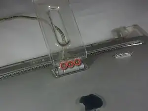
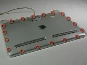
Place the Cinema Display so that it is lying on its face and the feet are pointed away from you.
-
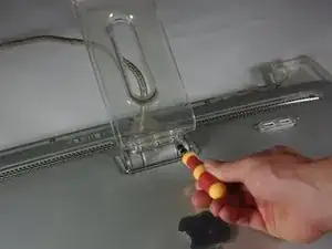
Remove the three screws (9.52 x 4.43mm) that connect the back foot to the hinge using the Hex Key.
-
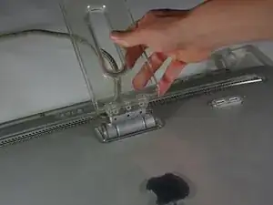
Remove the back foot from the hinge mount by grabbing the foot and pulling upwards.
-
-
-
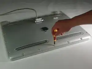
Remove the eighteen (5.25 x 4.43 mm) screws around the edge of the backplate using the Hex key.
-
Disconnect the small white connector leading to the display's Power button.
-
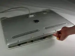
Gently lift the backplate off of the display. Completely remove the backplate and set it aside.
-
-
-
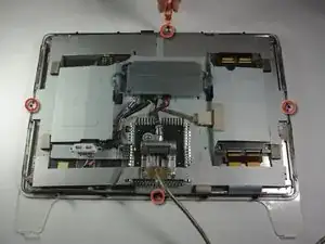
Use a Phillips #2 screwdriver to remove the four (9.52 x 3.43 mm) screws on the outer rim of the metal cover.
-
Next, remove the four cover (11.91 x 2.89 mm) screws located at the corners of the metal cover using the Phillips #2 screwdriver.
-
-
-
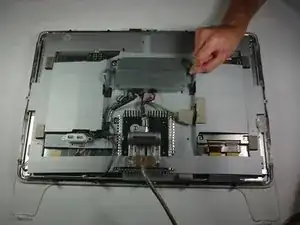
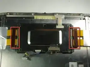
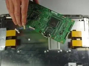
Unplug the large brown plug in the center-right, that connects the control board to the rest of the display.
-
Unplug the blue and gray plug on the right side of the control board. Repeat with the left side.
-
-
-
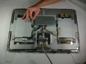
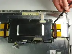
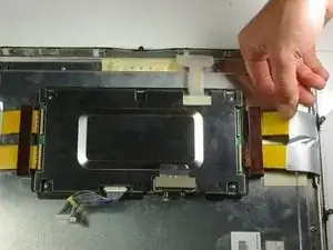
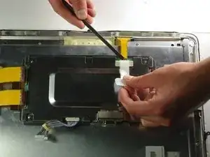
Pull the previously removed tape out from the metal box with your hand.
-
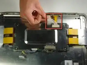
Peel back the white plastic cover located on the tape plug and unplug the tape plug on the right side of the unit using the spudger.
-
-
-
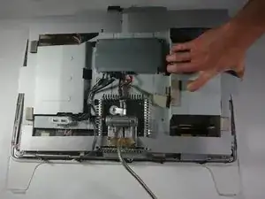
Unscrew the four screws (4.79x2.33mm) on the metal box using the Phillips #2 screwdriver.
-
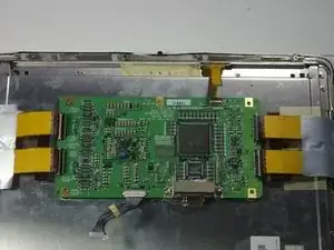
Lift the metal cover off to reveal a circuit board.
-
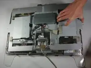
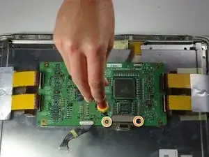
Remove the two terminal screws (4.79x2.34mm) using the Phillips #2 screwdriver.
-
-
-
Remove the terminal cover.
-
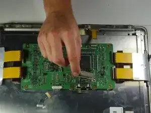
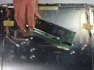
Remove the circuit board from the right side of the unit by gently lifting it out.
-
-
-
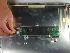
Turn your attention to the left side of the cinema display.
-
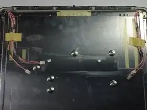
Using your fingers, unplug the small white plugs with pink wires from the top and bottom of the circuit board.
-
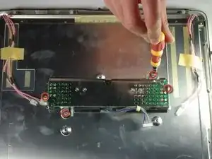
Using the PH 2 screw driver, remove the four screws (6.9 x 2.55 mm) holding down the circuit board.
-
Remove the circuit board by gently lifting it from the display.
-
-
-
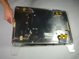
Lift the screen from the surrounding front cover by sliding your fingers between the two pieces and lifting.
-


To reassemble your device, follow these instructions in reverse order.
2 commenti
hello! where can i buy lcd screen for m8149?
Does anyone know where to get an inexpensive LCD replacement. Mine went primarily magneta except for the outer edges after zapping the pram?! Totally bummed as I bought a DVI to ADC power source and now the monitor is useless in it’s current state. C’est la vie!
le_grand -
Mine had hex head screws instead of Phillips head.
Bill Greene -
Hex 2.0 screws here too!
dietrichbatista -