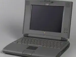
Introduzione
-
-
Slide the release button toward you and pull out the main battery from the right battery bay of the computer.
-
Repeat the procedure for the second battery, if installed, in the left battery bay of the computer.
-
If a PCMCIA card is installed, eject the card first, then remove the PCMCIA card cage from the left battery bay.
-
-
-
Using a T8 torx driver, remove the middle two bottom housing screws
-
Using a small flat-blade screwdriver, lift the front of the keyboard and pull it forward slightly.
-
Rotate the keyboard so that it is perpendicular to the top cover.
-
Release the locking tabs on the two keyboard cable connectors and disconnect the cables from the motherboard
-
Lift off the keyboard.
-
-
-
Using a T8 torx driver, remove the hard drive mounting screw.
-
Using a small flat-blade screwdriver, pry up the front of the hard drive and slide it forward.
-
Lift the drive partway out of the unit and disconnect the hard drive cable.
-
Remove the hard drive.
-
-
-
If you are replacing the hard drive, remove the four screws and remove the hard drive bracket and insulator.
-
-
-
Using a T-8 torx driver, remove the two floppy drive screws.
-
Using a small flat-blade screwdriver, pry up the cable end of the floppy drive and slide the drive to the left.
-
Slide the drive forward slightly and lift it partway out of the unit.
-
Disconnect the floppy drive cable from the motherboard and remove the drive.
-
If you are replacing the floppy drive or floppy drive cable, release the locking tabs and disconnect the cable from the drive.
-
-
-
Open the unit and rotate the display assembly as far back as it will go.
-
Using a flat-blade screwdriver and your fingers, press in on both sides of the wide end of the right clutch cover and release the two front latches.
-
Rotate the clutch cover up, release the third latch, and remove the cover.
-
Repeat for the other clutch cover.
-
-
-
Using a small flat-blade screwdriver, pry up the display access cover at the three slots in the front of the cover.
-
Remove the display access cover.
-
-
-
Disconnect the interconnect to logic board cable.
-
Using a T-8 torx driver, remove the two display mounting screws.
-
Slide the display assembly to the left so that the right clutch clears the loop of the interconnect to logic board cable.
-
Remove the display assembly.
-
-
-
Using a T-8 torx driver, remove the two rear panel screws.
-
Pull the center base cover forward slightly and slide it to the right to release the two screw carriers.
-
Remove the center base cover.
-
-
-
Rotate the feet to the up position.
-
Using a T-8 torx driver, remove the screw located under each foot.
-
Remove the four screws at the front edge of the bottom case
-
Remove the remaining screw on the inside top edge of the case.
-
Carefully lift and rotate the top case toward you and disconnect the track pad cable from the motherboard.
-
Remove the interconnect to logic board cable from the opening for the right clutch.
-
Remove the top case.
-
-
-
With a T8 Torx driver, remove the three mounting screws on the EMI shield.
-
Using a small flat-blade screwdriver, pry up and remove the daughterboard EMI shield.
-
-
-
Remove the plastic retainer bar.
-
You will need an IC extractor. I do not recommend using a flat head screwdriver
-
Place the legs of the IC extractor in the notches at the end of the daughterboard and pull up.
-
-
-
Remove the two screws from the plastic retainer bar.
-
Gently but firmly slide the plastic retainer bar away from the RAM card to release it.
-
Insert the IC puller along the two notches on either side of the RAM card.
-
Gripping the IC puller firmly, pull straight up to remove the RAM card.
-
-
-
To remove the modem card, place the legs of the IC extractor in the notches at the end of the board and pull up.
-
-
-
Disconnect the interconnect to logic board cable from the motherboard and remove the cable.
-
-
-
Using a T-8 torx driver, remove the three right side panel mounting screw.
-
Lift the panel slightly, slide it back, and remove it from the CPU stiffener.
-
Using a T-8 torx driver, remove the three left side-panel mounting screws.
-
Slide the panel to the left and remove it from the CPU stiffener.
-
-
-
Unlatch the left side panel from the back panel.
-
Rotate the feet to the up position.
-
Lift the CPU stiffener straight off the unit.
-
-
-
Remove the motherboard mounting screw and standoff.
-
Carefully pry the motherboard from the positioning peg located below the standoff.
-
Slide the board forward and lift it out.
-
-
-
Carefully disconnect the microphone cable from the interconnect board.
-
Using a small flat-blade screwdriver, pry up and remove the microphone assembly.
-
-
-
Using a small flat-blade screwdriver, pry up and remove the backup battery cover.
-
Carefully disconnect the backup battery cable.
-
Remove the cable from the cable guides.
-
Pry up and remove the backup battery and cable.
-
-
-
Using a T-8 torx driver, remove the front two mounting screws.
-
Disconnect the trackpad cable assembly and remove it from the unit.
-
Using a T-8 torx driver, remove the remaining two mounting screws
-
Pry up and remove the trackpad actuator assembly.
-
With your fingers, push up from underneath the trackpad logic board and remove it from the top case
-
-
-
Disconnect the speaker cable from the interconnect board.
-
Remove the bottom two bezel mounting screws.
-
Pry off the two rubber bumpers and remove the top two bezel mounting screws.
-
Pull the display bezel forward and lift it off the rear housing.
-
-
-
Remove the four mounting screws.
-
Disconnect the backlight cable from the inverter board.
-
Lift the display from the rear housing.
-
-
-
Remove the two mounting screws
-
Disconnect the interconnect to inverter cable and the backlight cable.
-
Remove the inverter board.
-
-
-
Disconnect the interconnect to display cable and the interconnect to inverter cable.
-
Remove the two mounting screws.
-
Remove the interconnect board.
-
-
-
Disconnect the interconnect to inverter cable from the interconnect and inverter boards.
-
Remove the cable from the back housing.
-
-
-
Disconnect the interconnect to display cable from the back of the display.
-
Remove the cable.
-
-
-
Remove the mounting screw for the right clutch and remove the clutch.
-
Repeat for the left clutch
-
To reassemble your device, follow these instructions in reverse order.