Introduzione
If using RRF3 (which you should be) you will need to update the BLV NeoPixel board.
-
-
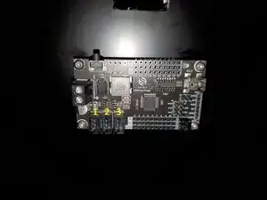
Add a jumper to "UVCC to 5V". If you skip this step you will not be able to flash the board.
-
Download the sketch from Github and extract the zip file. Open it in Arduino IDE
-
Board is "Arduino Pro or Pro Mini"
-
Processor is "ATmega328P (5V, 16 MHz)"
-
Upload the sketch to the board
-
When upload is complete, remove the jumper.
-
-
-
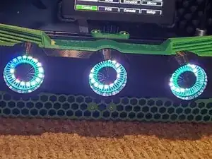
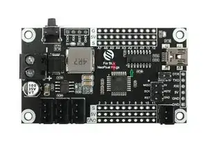
Left(Heatbed) connects to port #3 on the BLV NeoPixel board
-
Middle(Hotend) connects to port #1 on the BLV NeoPixel board
-
Right(print status) connects to port #2 on the BLV NeoPixel board
-
-
-
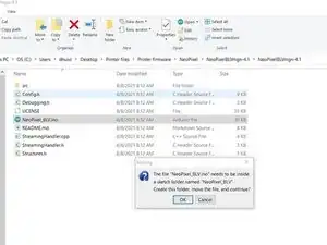
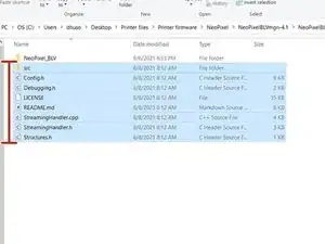
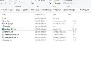
You might receive an error saying you need "NeoPixel_BLV.ino needs to be in a folder named NeoPixel_BLV". You have 2 options.
-
This will create a new folder and move the sketch into the newly created folder. Click OK than close Arudino IDE. Move the highlighted files and folder into the new folder "NeoPixel_BLV". You can now reopen the sketch and it should compile without issue.
-
You can also rename the sketch's parent folder to "NeoPixel_BLV". When you open the sketch you won't receive the error.
-
-
-
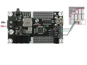
Because the CH340 drives RX to ~4.5v it doesn't communicate with the Duet 3. To remedy this you need to either cut the trace or de-solder the pad on the CH340(green) or on the ATMega(red). I would suggest de-soldering the pad on the CH340 because it's easier.
-
In addition to the current wiring schematic you'll also need to to connect the TX from the Arduino to RX on the duet
-
Arduino RX > Duet 3 io1.out
-
Arduino TX > Duet 3 io1.in
-
Arduino GND > Duet 3 io1.GND
-
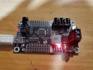
After the modifications you will no longer be able to upload a sketch using the USB port. You have to use a FTDI serial adapter and connect it to the 6 header pins next to the USB port.
-
-
-
For firmware versions prior to RRF 3.4.
-
If using IO_0: M575 P1 S1 B57600.
-
If using IO_1: M575 P2 S1 B57600
-
For firmware versions RRF 3.4 and later
-
If using IO_0: M575 P1 S0 B57600.
-
If using IO_1: M575 P2 S0 B57600
-