
Introduzione
This guide is intended to give in-depth steps for fixing a broken Cherry MX Red switch on a k70 corsair keyboard. This process involves soldering iron and thus has been given a difficulty rating of "difficult."
-
-
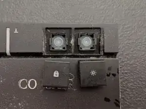
This is most effectively done with a key cap puller. However you can also use an IFIXIT opening tool.
-
The IFIXIT opening tool is especially useful in removing the brightness adjuster and windows lock in the top right of the keyboard.
-
-
-
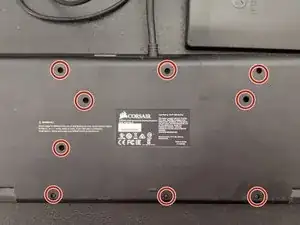
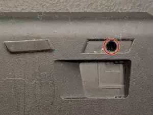
Flipping over the keyboard reveals eleven visible screws and two hidden underneath the rubber feet.
-
To make sure you do not lose track of the screws it is best practices to put them in something spill resistant and if possible magnetic
-
-
-
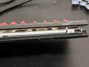
Using the IFIXIT opening tool work to separate the plastic bezel from the main body of the keyboard.
-
This is one of the harder parts of the disassembly. While it will feel like it is being held together by another screw there is none.
-
Work carefully and diligently as not to break an plastic tabs that are holding the bezel down.
-
-
-
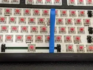
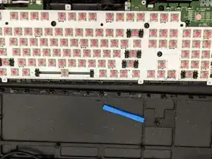
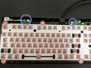
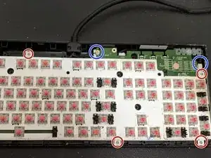
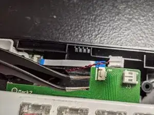
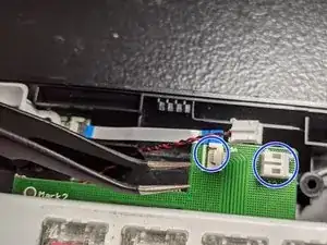
Underneath the bezel there are three cables highlighted and blue and seven screws that need to be removed.
-
The screws can be removed using the same triple-point y000 driver bit as all the screws that will proceed.
-
As for the cables these can be removed using the IFIXIT tweezers.
-
-
-
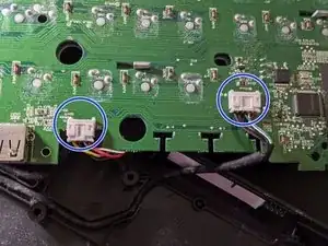
After removing the front cables and screws we are now able to flip over the pcb and view the back.
-
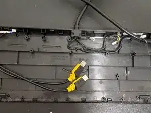
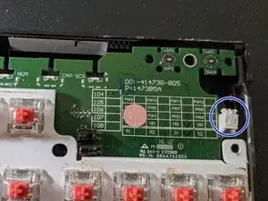
There are two relatively large cables known as "daughterboard cables" on the back of the pcb.
-
These two cables can be easily removed by either using you fingers or with the IFIXIT tweezers.
-
-
-
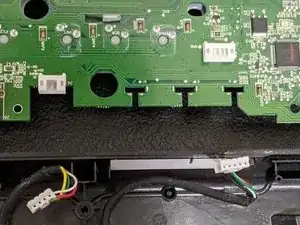
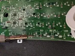
Flowing the disconnection of the daughterboard cables pcb unit can now be removed.
-
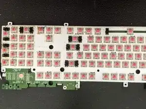
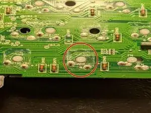
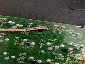
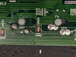
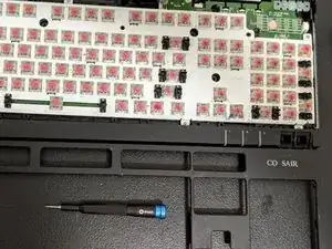
The next vital step is to locate the soldering joints connected to your broken switch. This is best done with a magnifying device as the identification numbers can be hard to read. In this case the broken switch is labeled "app"
-
-
-
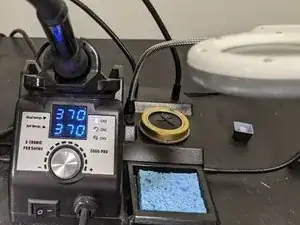
Soldering Iron: 370 Celsius
-
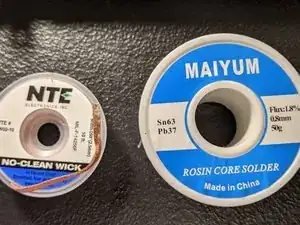
Solder: Rosin Core
-
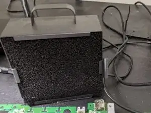
Fume Extractor: 120mm fan
-
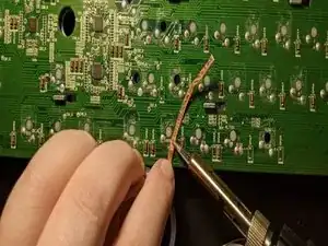
Wick: copper wire coated with rosin flux
-
-
-
To remove the old solder place the wick over the solder joint and heat with soldering iron. You might have to press relatively hard.
-
Once the majority of the old solder is removed use the tip of the soldering iron to poke a hole through the wick into the solder joint to clear it out completely.
-
-
-
As we have flux infused solder we do not need to use extra flux as well. Though I note this because it is much better to have it if your solder is not infused.
-
When soldering make sure not to hold the soldering iron for too long on the now component as this can cause damage.
-
Tinning the tip, can be done by rubbing solder on the tip of the iron and then using the cleaning sponge to help remove and solder residue. This helps make cleaner joints.
-
-
-
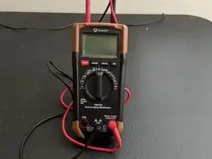
To make sure that you solder joint is correctly connected you can use a multimeter to test the continuity.
-
-
-
The pcb can now be placed in to the chassis once gain after the continuity test has been completed.
-
Once the pcb has been lined up with the threads begin to replace the screws. Make sure to not to cover up any of the cables that you need to plug back in.
-
-
-
After all the wires are plugged in test if the keyboard turns on.
-
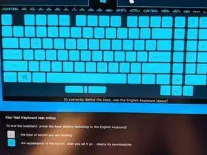
Connect via usb to a computer and pull up a keyboard tester. This allows you to check all of you keys to make sure they are in working order.
-
If all keys are working correctly finish tightening the screws and replace the bezel.
-
-
-
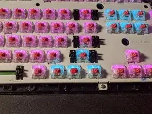
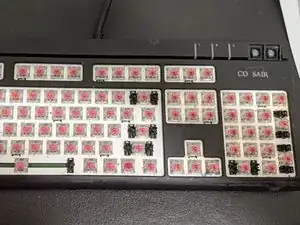
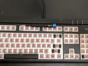
After replacing the bezel on to the chassis begin setting the keys into their proper spots.
-
-
-
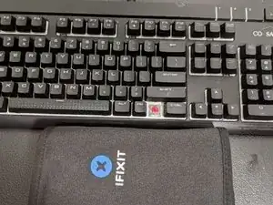
Using 3D printing is a great way to make plastic components that are either broken or missing.
-
On this particular keyboard the windows key for the replacement switch is also missing so I printed one.
-

7 commenti
holy $@$* i just wanted a replacement what is this LOL. But by all means it sure would work.
sfadsdf -
Lol sorry this was actually made as a project for my engineering technical writing class. So it had particular requirements that had to be followed. Tbh never expected anyone to look at it besides my engineering professor.
hmm lol i guess ill give it a try
bansku -
Very helpful. I wasn't certain if the switches were socketed or soldered, but this answered my question! Good luck in your studies!