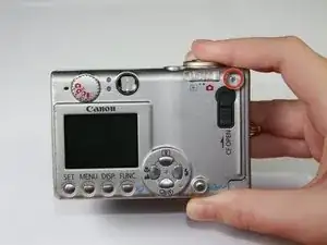
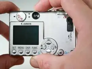
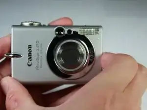
Introduzione

This installation guide will help you remove your broken LCD and install in a new replacement.

  1. jIMwnyWSI3SXoSbo
    jIMwnyWSI3SXoSbo
    4SOZrVvgxu5N2MSw
    • Turn the camera with the bottom side facing up.

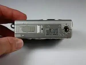
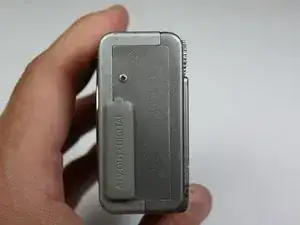
    • Locate the panel labeled "Batt. Open"

    • Place your finger on the panel and slide it in the direction of the arrow.

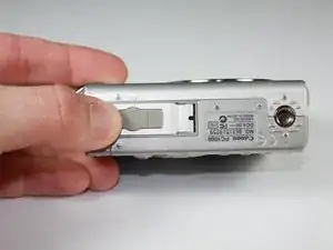
    • The slot will swing open revealing the battery pack.

  2. 6YAXDjDmausnZyqf
    • Pull the orange lever and the battery will spring out slightly.

  3. AyWNI1HnCVhIpWyd
    • Grasp the battery and fully pull it out of its slot.

    • When placing the new battery back in the slot, the arrow on the battery must align with the arrow on the camera.

  4. cFbwehVWr4Nw2eAQ
    • Start by laying the camera flat with the LCD screen facing up.

    • Using the Phillips #0 screwdriver, remove the 3.8mm screw in the upper right corner.

  5. dvSTvPBMAhgQZjtE
    • Position the camera with the bottom facing up.

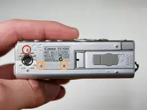
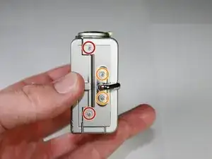
    • Twist the screwdriver counter-clockwise to remove the 4.8mm screw.

    • Repeat to remove the two 2.3mm screws.

  6. kPvy1AKNUkMBuCrq
    kPvy1AKNUkMBuCrq
    MVPdPUXEVxHuhHam
    • Position the camera so that the rubber "AV Out Digital" tab is facing upward.

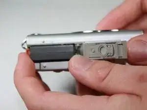
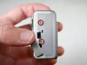
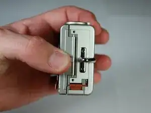
    • Slide the rubber tab to reveal the bottom screw.

    • Using the screwdriver, remove the two 3.7mm screws.

  7. y3FmPWfWDFVpxSXW
    • Turn the camera with the back side facing you.

    • Grip the edges of the back plate, and carefully slide it off.

    • If there is any resistance in movement, double check there are no screws left in the chassis.

  8. QxQDyoIhyojEJOIn
    QxQDyoIhyojEJOIn
    TBT15nHHgYNNGr3i
    • Orient the camera as in the picture.

    • Remove the two 2.3mm outer screws using the Phillips #0 screwdriver.

    • Remove the two 3.8mm screws near the strap bracket.

    • Remove the small panel covering the mounting bracket.

    • Remove the door covering the memory card.

  9. ZMFFEAnjfkGTAbuu
    • Rotate the camera so that the bottom side is facing you.

    • Remove the 3.8mm screw below the mounting bracket using the Phillips screwdriver.

  10. SxirhUieGsC6GMvQ
    • Rotate the camera so that the front is facing you.

    • Grasp the sides of the front cover and carefully pull the front panel off of the camera.

  11. vVxdTJ2DR5FsOg2N
    vVxdTJ2DR5FsOg2N
    MYYldMokv1lBWAqC
    • Position the camera so that the motherboard is facing you.

    • A fingernail or spudger can be used to remove the plastic flap covering the motherboard.

  12. 6AkhaxXYpNkNQ1AJ
    6AkhaxXYpNkNQ1AJ
    NwlZnjCW61YiSX6a
    • Turn the camera so that the bottom side is facing you.

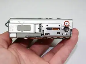
    • Remove the 2.1mm screw using the Phillips #0 screwdriver

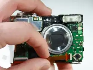
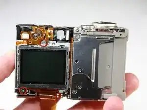
    • Grab the sides of the bottom panel and lift to expose the ribbon cable.

  13. oWlJrjYYAVJXNNyt
    oWlJrjYYAVJXNNyt
    qQ6FrvVFRkGCtSPv
    • Turn the camera so that the motherboard is facing you.

    • Using your fingernail, open the black clip holding the ribbon cable.

    • Gently pull out the ribbon cable in the direction of the cable using your fingers or tweezers.

  14. NjVqINWY5AnMBRO2
    • Turn the camera so that the LCD screen is facing you.

    • Remove the two 2.1mm screws on the aluminum tabs of the LCD screen using a screwdriver.

  15. IHRAACgEu5wuyOiJ
    IHRAACgEu5wuyOiJ
    BJQwZDryWRfwHkKW
    • Using a pair of tweezers, carefully pull the top ribbon cable out of the slot.

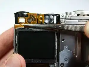
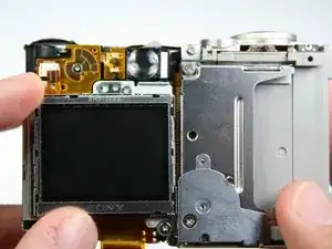
    • Grasp the sides of the LCD screen and lift off of the camera.

Conclusione

To reassemble your device, follow these instructions in reverse order.

kubayubay

Membro da: 24/01/11

101 Reputazione

0 commenti