Introduzione
-
-
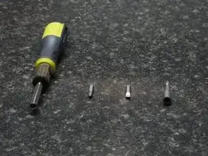
You will need:
-
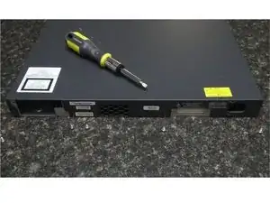
Phillips bit (PH2 size)
-
Flathead bit (size 6)
-
Socket bit (Size 1/4)
-
Multi-bit Screwdriver
-
-
-
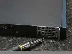
Using the Phillips bit, remove both brackets (if present) and the bolts installed on the left and right sides of the switch.
-
-
-
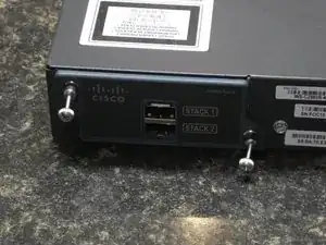
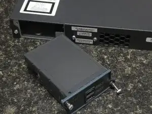
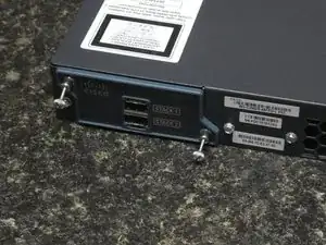
Your switch will have either a stacking module or blank cover at the back.
-
Loosen the two thumbscrews (using your screwdriver with the Phillips bit to assist if they are tight)
-
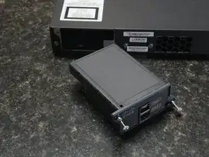
Using both loose screws, gently but firmly pull the module out of its slot.
-
-
-
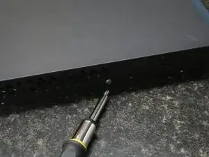
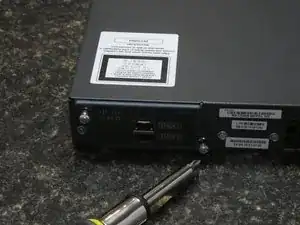
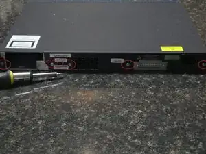
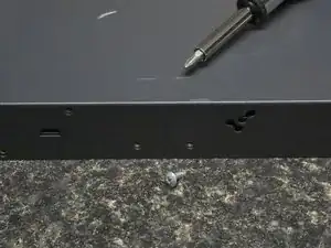
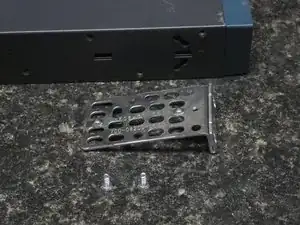
Using the flathead bit, remove the five chassis screws.
-
There are two at both ends, one next to the DC power socket, and two between the stack slot and fan exhaust.
-
-
-
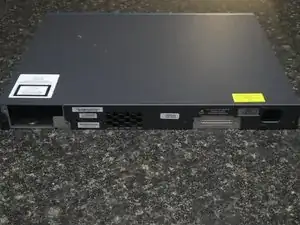
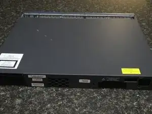
With all screws removed, the top cover should be free to slide to the rear, and can then be lifted away from the rest of the chassis, exposing the internal hardware of the switch.
-
-
-
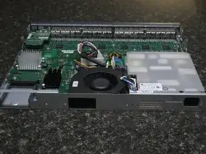
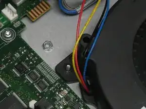
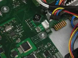
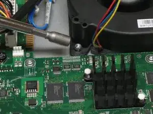
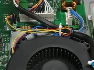
The fan assembly connects to the motherboard using a cable with four wires.
-
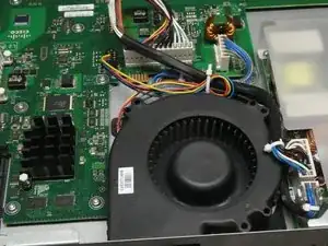
Familiarize yourself with the cables surrounding the fan assembly. These should not be moved around excessively in the next steps, nor should they be tampered with.
-
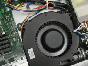
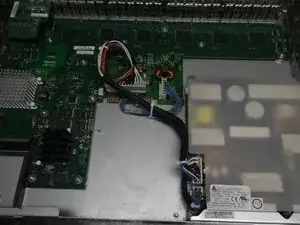
Note the two nuts securing the fan assembly to the chassis from above.
-
-
-
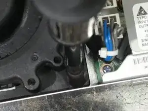
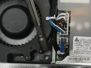
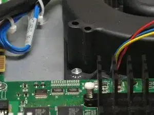
Using the 1/4 socket bit, remove the two nuts securing the fan assembly.
-
Take care to prevent the nut closest to the Power Supply from being knocked near the internals of the Power Supply.
-
-
-
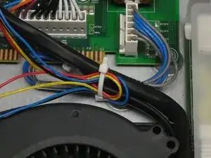
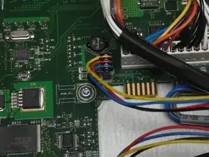
The slack on the Fan cable may be tucked behind a cable tie.
-
Remove each wire individually to free the cable.
-
Remove the connector at the end of the from its header on the board.
-
-
-
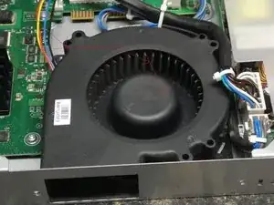
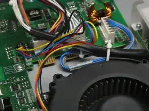
Lift the side of the Fan Assembly on the left (facing the rear of the switch), then slightly raise the right side, and lift up and away from the Power Supply.
-
-
-
Position the new Fan so that the right side (closes to the Power Supply) is angled down towards the bottom of the chassis.
-
Slide it under the Power Supply cable so that the cable sits on top of the edge of the Fan Assembly.
-
Lower in the rest of the Fan, and line the holes up with the bolts on the chassis, and lay the fan onto the bolts so that they poke through and hold the fan in its appropriate position.
-
-
-
Since the nuts may not be magnetic, start with the nut closest to the Power Supply. Position it on top of the bolt as closely to flat as possible, and use the socket bit to screw the nut in and only mildly tighten.
-
This might take a few attempts. The nut may bounce away. Remove the Fan Assembly to retrieve the nut and try again until you are able to get it secured.
-
Secure the other side of the fan using the other nut.
-
-
-
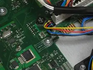
Connect the connector in the same orientation as before.
-
Tuck the excess slack on the wires under the cable tie, being careful to allow enough slack to remain to prevent strain on the wires.
-
-
-
Place cover onto the chassis (positioned slightly to the back, same as when it was removed)
-
Slide to the front to close the cover.
-
-
-
Insert the Module into its slot in the same orientation that it originally was.
-
Do not use a screwdriver. Hand tighten the screws to secure the Module or Cover into place.
-
-
-
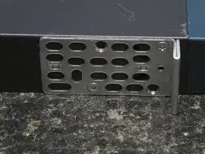
Use Phillips bit to fasten the remaining Chassis screws in, and install the brackets on both sides of the Switch.
-
-
-
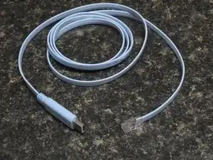
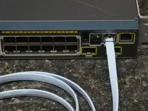
Power on the Switch. Connect your console cable and launch your serial terminal. (If you use SSH to access your switch, log in once it is finished booting).
-
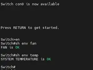
Elevate, and run the following commands:
-
sh env fan
-
sh env temp
-
Both should show OK.
-


To reassemble your device, follow these instructions in reverse order.